If you have read Bob Orban's ancient post on comp.dsp what you posted in #1 is not optimal. I'm tired after years of trying to help people, do whatever you want.
Thank you, Scott, for reminding me why I no longer spend much (any?) time on this forum. I'd truly forgotten what a PITA DIY audiophiles can be.
"HOW DARE YOU NOT READ 30 PAGES OF THREADS ON THE INTERNECINE DISCUSSION OF X TOPIC FROM 5 YEARS AGO BEFORE POSTING!!!!11111RAWR!!!!!"
Maybe you just aren't aware of how you come off? You have not posted anything helpful, so perhaps best not to post at all. Otherwise, I'd love to hear how to send the 6 coefficients necessary for the biquad directly to LADSPA. If not, I'll keep using Charlie's method.
Bill, thanks for the link.
What you guys don't realize is that Charlie has done this entirely as a favor to me, as he is a 'perfect sound forever' digital sort of guy 🙄
I'm an analog dude, but I also like the flexibility of my digital setup, which cost me the princely sum of $45 (Rpi2, old H/K receiver, some wires, some free speakers, some MDF) and will blow most spendy systems out of the water. I've been using Charlie's LADSPA plugins directly in ALSA, so it's quite easy for me to implement an RIAA filter there, also, then I can bring my analog into my room corrected active setup!
I'm quite happy to get some feedback on the best, most flexible way to do that, preferably without having to read 30 pages of forum posts, most of which are quite off-topic of what I care about (implementing a filter).
Thanks,
James
PS if you're interested to learn more about how I implemented my rpi music server, you can read more here:
Raspberry Pi Music Server With Built-in Crossover and DSP : 12 Steps (with Pictures) - Instructables
which has step by step instructions.
On the pi3, the method is a bit different, which charlie documents here:
https://www.diyaudio.com/forums/pc-...form-using-raspberry-pi-hats.html#post5710184
this may not be necessary as I'm told newer kernels will output multichannel hi-rez audio through HDMI natively (without kernel rebuilding)
Folks, here is a retrospective on all of this. I have demonstrated how to implement an RIAA EQ correction curve using my ACDf IIR filter LADSPA plugin. It's practical, more than satisfactory, and provides some adjustability to suit one's listening preferences at several frequencies. Now it seems that some folks think it is important to be within a tenth of a dB and with a few degrees of some "perfect" EQ curve. Fine. But I'm not really all that concerned with this level of accuracy here. Who knows if the recording, on the disc, is faithful to such a fine tolerance anyway.
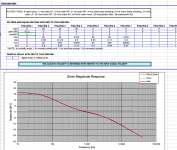
I will explain how I came to the EQ curve (apart from what I explained in post #1 of this thread). The 1kHz level is at 0 dB. Below there is a first order rise. I can implement this using my ACDf plugin (also works for miniDSP) as a first order "bass shelf". There is 20dB of boost below the shelf. The center frequency of the shelf is the geometric mean of the limiting frequencies. In this case, the boost runs between 50Hz and 500Hz, and the geometric mean is 158.114 Hz. Initially I did the correction by eye and came up with 155 Hz, so pretty close. The other correction occurs above 2.1kHz, and has a slope of -6dB/oct. I implemented this using a first order lowpass filter. Again, close enough for me. I have read about additional minor corrections where this flattens again at some frequency like 50kHz. There are two reasons why I would not bother with this: (1) It's too high in frequency to have anything but a very minor impact of the phase response above 10kHz, and (2) with digital EQ, as I mentioned in the first post, there is a zero at the Nyquist frequency. You cannot place a zero higher in frequency or do anything up there for that matter. For 96kHz, Nyquist is at 48kHz so you are more or less constrained by the sampling rate. Sure you can use some ridiculously high rate like 196k or higher, but really folks... this is more than splitting hairs IMHO. I would be happy explain how it can be done using another shelf instead of a 1st order LP if someone would like to try it.
With only those two corrections, the EQ curve only loosely follows the EQ target. But perhaps that is the kind of correction that was used by the record companies... and is therefore the one to use. I really don't know. The EQ can be brought closer to the target using the PEQ bands that I specified in post #1. By choosing the PEQ gain anywhere between 0dB (no correction) and 2.5dB (full correction) you can bring in the curve at the inflection points to suit your own taste, feeling, sense, etc.
If anyone wants to engage in a productive discussion about this EQ scheme, how to implement it or tweak/improve it, I am happy to engage.
Have fun and don't take yourselves too seriously. Remember, DIY audio is just for our entertainment.
.
The curve you usually see, with the sharp corners isn't how the frequency response should look, it just shows the "ideal" or asymptotic curve. The real curve is much smoother and it should never become horizontal in the middle. That smooth one is the one you should target!
Look here for example:
HiFi Loudspeaker Design
In any case, expressing the curve as a few standard filters is very useful. I'm no fan of plugging in precalculated biquad values. From a user perspective it's so much better to state what a filter should do (with poles and zeros for example, or even higher level with just a name like HighpassLR4) and then letting the sofware calculate whatever biquad coeffs are needed.
Managed to get a reasonable looking curve with 3 biquad filters. This gets me within 1/2db after 30hz (a flatter low frequency curve makes more sense to me)
There are probably more ways to do this, but this is what I thought of. If you're using ACDf, you have to update the sample rate, otherwise Nyquist steps in and rolls off frequencies above 10k.
Now that I have an interface, time to see if I can make it work on the pi 🙂
There are probably more ways to do this, but this is what I thought of. If you're using ACDf, you have to update the sample rate, otherwise Nyquist steps in and rolls off frequencies above 10k.
Now that I have an interface, time to see if I can make it work on the pi 🙂
Attachments
Managed to get a reasonable looking curve with 3 biquad filters. This gets me within 1/2db after 30hz (a flatter low frequency curve makes more sense to me)
There are probably more ways to do this, but this is what I thought of. If you're using ACDf, you have to update the sample rate, otherwise Nyquist steps in and rolls off frequencies above 10k.
Now that I have an interface, time to see if I can make it work on the pi 🙂
I think you made a slight mistake in ACD with the driver FRD data. In your plot the SPL of the driver looks to be constant at 1dB. My guess is that you entered something like 1,1,1 and 20000,1,1 for the driver FRD data... With 1 dB of boost built into the fake driver, your EQ curve will be off 1dB in magnitude everywhere, although that is not really a problem at all since you will be using another gain stage from the audio interface.
When you enter fake driver FRD data you probably should enter 0dB and 0 degrees phase angle, e.g. X Hz, 0 dB SPL ,0 degrees and Y Hz, 0 dB SPL ,0 degrees in the FRD data sheet in the driver worksheet. In place of X enter a frequency at or just above the plot minimum, and for Y enter a frequency at or just below the plot maximum.
Otherwise, looks good! And of course you now have the ability to tweak the EQ curve at will.
By the way, where did you get the data for your "Ideal" reference curve?
Last edited:
Good call, an easy fix 🙂I think you made a slight mistake in ACD with the driver FRD data. In your plot the SPL of the driver looks to be constant at 1dB. My guess is that you entered something like 1,1,1 and 20000,1,1 for the driver FRD data... With 1 dB of boost built into the fake driver, your EQ curve will be off 1dB in magnitude everywhere, although that is not really a problem at all since you will be using another gain stage from the audio interface.
When you enter fake driver FRD data you probably should enter 0dB and 0 degrees phase angle, e.g. X Hz, 0 dB SPL ,0 degrees and Y Hz, 0 dB SPL ,0 degrees in the FRD data sheet in the driver worksheet. In place of X enter a frequency at or just above the plot minimum, and for Y enter a frequency at or just below the plot maximum.
Otherwise, looks good! And of course you now have the ability to tweak the EQ curve at will.
By the way, where did you get the data for your "Ideal" reference curve?
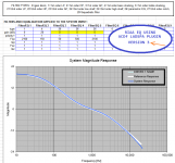
the reference curve came from the site @henrik linked, HiFi Loudspeaker Design as he actually has numbers that are spreadsheet-able
Ah, thanks! Got it. So, using that data, I present the fit I achieved with the filters I listed in the first post, but without the PEQ bands, at a sample rate of 96k Hz. I set the gain of each PEQ stage to 0 dB so that it will have no effect. The only minor change was in the frequency of the low shelf, which I changed from 155 Hz initially to 158 Hz in this version.
Please see the attached plot that compares the two.
I will try to create tabulated values that compare my EQ and the reference one at the link you gave me, and/or plots of the difference between the two. I will have to get to that later tonight.
NOTE I am using version 3 of my LADSPA plugins. These are available at the link in my signatures. There have been a couple of changes since version 2...
.
Attachments
Last edited:
...
By the way, where did you get the data for your "Ideal" reference curve?
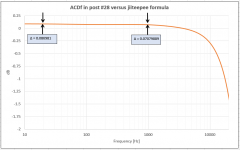
On LibreOffice formula :
Code:
=10*LOG(1+1/(4*PI()^2*x^2*0.000318^2))-10*LOG(1+4*PI()^2*x^2*0.000075^2)-10*LOG(1+1/(4*PI()^2*x^2*0.00318^2))-0.088982and -0.088982 is to adjust 0dB @ 1000Hz.
On LibreOffice formula :
where x = frequency in Hz (20, 21, 22, 23, .... 19997, 19998, 19999, 20000, ....)Code:=10*LOG(1+1/(4*PI()^2*x^2*0.000318^2))-10*LOG(1+4*PI()^2*x^2*0.000075^2)-10*LOG(1+1/(4*PI()^2*x^2*0.00318^2))-0.088982
and -0.088982 is to adjust 0dB @ 1000Hz.
Thanks for that. Comparison attached. If they were the same there would be a flat line at 0dB.
My method includes the low frequency offset that you attempt to zero out with the final term of the formula. I will look into why my response sags at the high end, but at least part of that is due to the zero at the Nyquist frequency I mentioned before.
.
Attachments
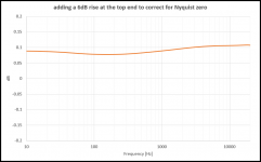
I was able to eliminate the top end rolloff by inserting a 6 dB rise centered above the audio band. This compensates for the zero at the Nyquist frequency within the audio band. See attached plot. The EQ curve now matches within about +/- 0.02 dB. Above the audio band the response rolls off into a notch at the Nyquist frequency.
This is only a solution for ONE sample rate (this is 96kHz). At another sample rate a different 6dB rise would be required because the zero will have changed in frequency. In any case I would not advise using a sample rate less than 96kHz for this application.
.
This is only a solution for ONE sample rate (this is 96kHz). At another sample rate a different 6dB rise would be required because the zero will have changed in frequency. In any case I would not advise using a sample rate less than 96kHz for this application.
.
Attachments
My method includes the low frequency offset that you attempt to zero out with the final term of the formula. I will look into why my response sags at the high end, but at least part of that is due to the zero at the Nyquist frequency I mentioned before.
That formula is for s-domain filter ....
...
I will look into why my response sags at the high end, but at least part of that is due to the zero at the Nyquist frequency I mentioned before.
.
This error in response comes from transfer method (BLT) related issue and without hard optimization you can fix it by just using high sampling. Orban used Remez Enhanced based approximation, Scott Wurcer some other method.
MZT/IIM has less error in magnitude response but, phase is wrong. In one biquad implementation these methods has one analog coefficient unused so one can improve the response by using this.
Last edited:
Hi,
What do you think of that?
Obviously the LF will be different because of the input stage of the DSP.
Target given by the equation given by @jiiteepee optimized fitting with Matlab.
Sampling rate 96kHz higher would be better but it looks like 20kHz is correctly captured.
3 biquads
Gain: 19.9dB
could be implemented with EQ APO: https://sourceforge.net/projects/peace-equalizer-apo-extension/
Filter 1: 1st LowPass Fc 50.00 Hz Gain 0.00 dB Q 0.50
Filter 2: HighShelf Fc 1031.632 Hz Gain 12.570 dB Q 0.467
Filter 3: Peaking Fc 24369.418 Hz Gain 1.645 dB Q 0.817

Edit with extended HF, very close to -3dB@40kHz.
Filter 1: 1st LowPass Fc 50.00 Hz Gain 0.00 dB Q 0.50
Filter 2: HighShelf Fc 1031.990 Hz Gain 12.570 dB Q 0.467
Filter 3: Peaking Fc 37794.908 Hz Gain 6.130 dB Q 0.559

What do you think of that?
Obviously the LF will be different because of the input stage of the DSP.
Target given by the equation given by @jiiteepee optimized fitting with Matlab.
Sampling rate 96kHz higher would be better but it looks like 20kHz is correctly captured.
3 biquads
Gain: 19.9dB
could be implemented with EQ APO: https://sourceforge.net/projects/peace-equalizer-apo-extension/
Filter 1: 1st LowPass Fc 50.00 Hz Gain 0.00 dB Q 0.50
Filter 2: HighShelf Fc 1031.632 Hz Gain 12.570 dB Q 0.467
Filter 3: Peaking Fc 24369.418 Hz Gain 1.645 dB Q 0.817
Edit with extended HF, very close to -3dB@40kHz.
Filter 1: 1st LowPass Fc 50.00 Hz Gain 0.00 dB Q 0.50
Filter 2: HighShelf Fc 1031.990 Hz Gain 12.570 dB Q 0.467
Filter 3: Peaking Fc 37794.908 Hz Gain 6.130 dB Q 0.559
Last edited:
Hi,
What do you think of that?
Obviously the LF will be different because of the input stage of the DSP.
Target given by the equation given by @jiiteepee optimized fitting with Matlab.
Sampling rate 96kHz higher would be better but it looks like 20kHz is correctly captured.
3 biquads
Gain: 19.9dB
could be implemented with EQ APO: https://sourceforge.net/projects/peace-equalizer-apo-extension/
Filter 1: 1st LowPass Fc 50.00 Hz Gain 0.00 dB Q 0.50
Filter 2: HighShelf Fc 1031.632 Hz Gain 12.570 dB Q 0.467
Filter 3: Peaking Fc 24369.418 Hz Gain 1.645 dB Q 0.817
...
Edit with extended HF, very close to -3dB@40kHz.
Filter 1: 1st LowPass Fc 50.00 Hz Gain 0.00 dB Q 0.50
Filter 2: HighShelf Fc 1031.990 Hz Gain 12.570 dB Q 0.467
Filter 3: Peaking Fc 37794.908 Hz Gain 6.130 dB Q 0.559
...
Hmm... you say could be implemented with EqualizerAPO, so, I guess you have not yet tried this..., IIRC (few years gone since played with EqualizserAPO), some filter type(s) does not like Fc go above 20kHz (EqualizerAPO is based on RBJ's filters). To round this (possible) limit you can use IIR command instead. https://sourceforge.net/p/equalizerapo/discussion/general/thread/e13f460d/ , https://sourceforge.net/p/equalizerapo/discussion/general/thread/8ef5573509/#8680/9337/d485/8a65

You need an input that has the right impedance and roughly the right noise matching for the used cartridge.
I've been doing software RIAA realtime EQ with biquads for a while now. I also played with ffmpeg's built in RIAA EQ and have measured quite a few carts and stylii with multiple test records and EQ methods. Here are some things I learned along the way, hoping that someone might find something useful in my ramblings.
- A simple linear NE5532 gain stage is very useful, with this you can use any type of line level input DSP, I have used the Shure/Wondom ADAU1701 and Linux PCs before but with this anything that can do the EQ will work
- Many biquads and other solutions are not accurate above 15kHz - you won't be able to decode JVC quadrophonic discs unless you get this right
- For this you want to go with the biquads from Scott's Linear Audio article - available here v10 sw appendix a tables and use at least a 96kHz sample rate
- Loading matters and is often not that straight forward - 47kOhm is not always great or even good. I have had success with 75k (Audio Technica) and no extra loading (Ortofon OMP). Some loadings might seem like they sound pleasing at first but then you measure and discover that they degrade frequency response overall
- Test records are worth their weight in gold. You'll need a few of them for cross referencing
- Capacitance is the enemy. Use low capacitance, well insulated wire and keep them very short
- Test records can help you find the correct loading and will help you correct for frequency response errors with a channel independant multiband EQ. This is very worthwhile with otherwise good MM carts.
- Getting both channels to sound identical helps a lot and tonality really improves if you straighten out the response by a few dB here and there
- You can have fun with crosstalk cancellation and reduce crosstalk by more than 10dB@1kHz with relatively low effort (plus a suitable test record)
- ffmpeg has a really good declicking algo included. It sure beats my Marantz SX72 by a lot. It can be used in realtime playback situations to great effect. Otherwise unlistenable records become very enjoyable again. Transients suffer, but not as much as I'd have expected.
- Implement this whole shebang in Henrik's excellent CamillaDSP - I still have to figure out how I can run filters on input channels instead of output channels
- Try my luck at decoding the DBX and CX encoded records I have purely with software. People have managed to decode DBX I and II in software, DBX Disc is just a version of DBX II with a low pass added somewhere. To me it seems quite cool to listen to DBX records with 90dB SNR, decoded purely in software. I tried my luck at this once but got stuck builing the filter chain.
- Expand my research on crosstalk cancellation. I achieved spectacular results on Audio Technica carts where crosstalk dropped by more than 10dB but I have yet to replicate this with a Technics P33 cart. It probably needs a few samples of delay added and it will probably be fine but I have yet to test this hypothesis
- Record some needle drops of well produced albums and compare the aggregate frequency spectrum to that of the CD version. This way I might be able to deduce a frequency deviation between LP and CD. This could be compared to the measured frequency response obtained from my test records. Maybe, just maybe, we could use specific, known-good albums available on CD and LP as a sort of "poor man's test disc", at least to look at frequency response errors...
...
- Many biquads and other solutions are not accurate above 15kHz - you won't be able to decode JVC quadrophonic discs unless you get this right
- For this you want to go with the biquads from Scott's Linear Audio article - available here v10 sw appendix a tables and use at least a 96kHz sample rate
- ...
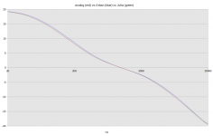
Do you mean error being less than 0.3dB above 15kHz has some meaning? Actually Orban's and Wurcer's RIAA coefficients has their max error at below 15kHz... here's Orban's biquad filter (Wurcer's biquad implementation behind the link you gave has similar response) compared against analog response and optimized MZT implementation (fs=44.1kHz):
Attachments
Last edited:
Yes and no. My hearing goes to 16k at best. I'm not physically able to hear any difference. So for playback of a regular record it's acoustically accurate as far as my hearing is concerned.Do you mean error being less than 0.3dB above 15kHz has some meaning?
My point is that software RIAA is often technically imperfect compared to analog implementations, in specific corner cases. A JVC CD-4 encoded record is a good example: it contains sound that is FM encoded into the groove from 18 to 45kHz. You need at least a 96kHz sampling rate for this to be reproduced and your EQ method needs to be moderately accurate up to 45k. I used ffmpeg's RIAA filter and discovered that it's band limited to 20 kHz regardless of input sample rate. This was really annoying with my B+K test record that goes beyond 30kHz. Scott's method works perfectly at 96kHz, I cannot vouch for other methods.
With any old analog RIAA implementation these things just seamlessly work.
At FS=44.1kHz everything is fine and dandy. Beyond that is where you get to see the difference. Most people will not mind or care 🙂Actually Orban's and Wurcer's RIAA coefficients has their max error at below 15kHz... here's Orban's biquad filter (Wurcer's biquad implementation behind the link you gave has similar response) compared against analog response and optimized MZT implementation (fs=44.1kHz):
...
My point is that software RIAA is often technically imperfect compared to analog implementations, in specific corner cases. A JVC CD-4 encoded record is a good example: it contains sound that is FM encoded into the groove from 18 to 45kHz. You need at least a 96kHz sampling rate for this to be reproduced and your EQ method needs to be moderately accurate up to 45k. I used ffmpeg's RIAA filter and discovered that it's band limited to 20 kHz regardless of input sample rate. This was really annoying with my B+K test record that goes beyond 30kHz. Scott's method works perfectly at 96kHz, I cannot vouch for other methods.
With any old analog RIAA implementation these things just seamlessly work.
...
Have you compared the response of the digital 96kHz RIAA filter you vouch for against analog RIAA filter?
By quick test in Octave, looks like Orban/Wurcer 96kHz filter has about 1.45dB error (absolute) against digital model of analog filter @ 45kHz ... (Orban's little (0.0001dB) less than Wurcer's) ... relative error stayed below 0.06dB all the way (1Hz-48kHz) for both filters (as expected).
Filter @ lower sample rates, as like 44.1kHz, just shows better the nature of the error coming from coefficient calculations ... if same method used then shape of the error usually stays in higher sampling but, of course, higher sample rate makes it smaller.
No, I never did that. The frequency response errors from my carts were way bigger than any error in the RIAA filter. I EQd both my analog preamp and later my digital RIAA filter after measuring frequency sweeps with a test record. Any smaller response error in the audible range would get hammered flat anyway.Have you compared the response of the digital 96kHz RIAA filter you vouch for against analog RIAA filter?
By quick test in Octave, looks like Orban/Wurcer 96kHz filter has about 1.45dB error (absolute) against digital model of analog filter @ 45kHz ... (Orban's little (0.0001dB) less than Wurcer's) ... relative error stayed below 0.06dB all the way (1Hz-48kHz) for both filters (as expected).
My requirement is not "perfectly flat @45kHz" but rather "good enough for CD4 records - so that I can see both FM sidebands left and right of the carrier frequency, roughly equally loud and loud enough to be above the noise floor".
Have you read Scott's article? I can really recommend it, you can get the PDF for €3 from the Linear Audio site. He goes through the entire process of designing the filters, literally "does the math" and includes all the test files and python scripts used as a download on the LA website.
https://linearaudio.net/article-detail/2240 and the downloads are at https://linearaudio.net/downloads. I'm not in any way affiliated with LA or Scott, I just found the books and this one article in particular a really good read.
True, but isn't that why you are supposed to use an IIR filter that is made specifically for the sampling rate you're using?Filter @ lower sample rates, as like 44.1kHz, just shows better the nature of the error coming from coefficient calculations ... if same method used then shape of the error usually stays in higher sampling but, of course, higher sample rate makes it smaller.
- Home
- Source & Line
- PC Based
- Phono preamp: RIAA EQ using IIR digital filters