Turn table had issues with lights flickering.
This turn table used touch buttons
Motor and all bulbs work. I tested them with 5v DC power.
Control board is simple. Not much soldered on there just can't figure out which component is bad.
One other thing I found out is that transformer is dead. Outputs like .012v or something close to 0v
I used one old charger that outputs 13v DC. Which is close enough to original 14v charger. When measuring PS supply voltage after rectifier diode Ii get 11v or so. Manual says it should be 9v. Maybe I am measuring wrong
When plugging in new 13v DC charger to the board I don't get any signs of life. Touch buttons don't lite up. I attached service manual.
Was hoping to step by step go through this circuit
Here is the link to service manual
https://www.google.com/url?sa=t&sou...Vaw2FBY7ax4ES90rV8q6BcNd9&cshid=1595395741320
I take it you connected the 13V charger to the full wave rectifier in the power supply which should output MINUS 9V (collector supply for the PNP BJT,s +emitter suppy for the NPN BJT,s ) ?
I would check the PS pass transistor AD162 which is a germanium power transistor they are apt to blow as is the germanium AC127 in the same circuit as you are complaining of "no lights " and there is a power light in the same circuit ---no light /no power unless the bulb itself is blown.
Thats -
Step 1.
Directly after the rectifier you ought to measure about the same (- 1V or so) DC voltage as you put into the rectifier. So at that point a 11V measurement could be plausible.When measuring PS supply voltage after rectifier diode Ii get 11v or so. Manual says it should be 9v. Maybe I am measuring wrong
After the regulator the voltage ought to be 9V. But when fed with 11Vdc the regulator might get in to trouble doing it's job. Did you measure the voltage after the regulator?
As you describe the transformer is suspect having failed. I've never heard that before in this type of player, but I can't rule that out being impossible.
The major causes of psu malfunction are:
- failing regulator (AD162)
- failing filter elco (470uF)
So you first ought to check if the AD162 is still good with your multimeter. Set it to "diode" measurement and check all connections of the transistor against eachother. Check for shorts and opens in both ways. The AC127 usually doesn't blow.
"The AC127 usually doesn't blow".
Having worked on germanuim transistors in every aspect they do "blow ".
Blow in my terms is not "blow up " but s/c--go open circuit depending on the circuit use ,your thinking of bombs or power supply filter capacitors which do BLOW ---up literally hitting the ceiling of my room , that's why I built a capacitor reformer for very old radios --it reforms them over a period of time.
"The AC127 usually doesn't blow".
Having worked on germanuim transistors in every aspect they do "blow ".
Blow in my terms is not "blow up " but s/c--go open circuit depending on the circuit use ,your thinking of bombs or power supply filter capacitors which do BLOW ---up literally hitting the ceiling of my room , that's why I built a capacitor reformer for very old radios --it reforms them over a period of time.
I was referring to the circuit in which the AC127 usually is not the failing part. The AD162 is more likely to fail.
Your right the AC127 isn't normally not a failing part in this design but in other applications like late fifties/mid sixties portable transistor radios they did fail regularly as I repaired many of them .
Have you measured the primary winding???
Almost all the old Philips transformers had a built in "fuse", which means a small plasticholder holding two thin spring like cores, which are soldered together at the end.
The plastic holder is just squeezed in the plastic coil former that holds the solder lugs.
If nothing else is wrong and the cores have sprung open, just resolder them again.
Can´t seem to find pictures online, so you´ll have to figure this one out for yourself 🙂
Last edited:
Looks like its labelled "Z" in the primary winding of the transformer schematic -
https://www.eevblog.com/forum/repai...-circuit/?action=dlattach;attach=148793;image
https://www.eevblog.com/forum/repai...-circuit/?action=dlattach;attach=148793;image
Correct... that's another pitfall... These thermal fuses prevent from extreme overheating of the transformer. There are no replacements, so if defect, you have to short them or try to find another transformer with an intact fuse.Almost all the old Philips transformers had a built in "fuse", which means a small plasticholder holding two thin spring like cores, which are soldered together at the end.
Resoldering those fuses won't do. You're making a joint with a meltingpoint way higher (about twice) than designed. You can do that, but then you must add a fuse (50mA or 100mA slow) in the primary circuit
Last edited:
That´s why I wrote "if nothing else is wrong" 🙂
The aging of the original solder often make them "go open" without any overheating. Have soldered a lot of these with low melting point solder.
But of course, you´re right. A 50mA slo-blo on the 2 solder lugs should be sufficient on a transformer of this small size 🙂
The aging of the original solder often make them "go open" without any overheating. Have soldered a lot of these with low melting point solder.
But of course, you´re right. A 50mA slo-blo on the 2 solder lugs should be sufficient on a transformer of this small size 🙂
I really appreciate all responses. I did read about the plastic fuse and located it on transformer.
Looks like I need to take more voltage measurements and post the values I am getting at each point of the diagram to help you help me)
I'll get to it in the evening today
Looks like I need to take more voltage measurements and post the values I am getting at each point of the diagram to help you help me)
I'll get to it in the evening today
Richard....
Star by setting your DMM in "OHM" and try to measure the primary. If it´s open, you where to start 🙂
Star by setting your DMM in "OHM" and try to measure the primary. If it´s open, you where to start 🙂
That´s why I wrote "if nothing else is wrong" 🙂
The aging of the original solder often make them "go open" without any overheating. Have soldered a lot of these with low melting point solder.
But of course, you´re right. A 50mA slo-blo on the 2 solder lugs should be sufficient on a transformer of this small size 🙂
Well, "if nothing else is wrong" ... then you gamble on "nothing goes wrong in future" too... My approach would be: get rid of the thermal fuse and install a "real" fuse

So transformer is disconnected from the control board
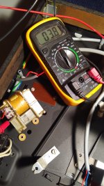
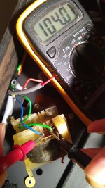
DC coil resistance is 4ohm
Ac coil is 104ohm
I measured resistance straight from copper coil terminals.
Does this mean transformer is a toast. 4ohm is a little low for this amount or cooper I think. But what do you think? I am not an electric engineer
DC coil resistance is 4ohm
Ac coil is 104ohm
I measured resistance straight from copper coil terminals.
Does this mean transformer is a toast. 4ohm is a little low for this amount or cooper I think. But what do you think? I am not an electric engineer
Attachments
Last edited:
That sounds like a typical power transformer to me.
I'd suspect something ELSE is an issue, and locate it.
I'd suspect something ELSE is an issue, and locate it.
Ok I'll look into heat fuse. But why am I getting close to zero DC voltage .
Ac terminals of transformer are definitely getting 110v. Definitely not a bad switch issue. But DC terminals or transformer are outputting 0- 0.012 v . Shouldn't I be able to read 14v on DC side of transformer
Or is it 14v ac. Sorry forgot. Transformer takes wall outlet 110ac outputs 14v ac and then rectifier diodes turn 14v ac into 14v DC. Am I right with this understanding of power supply operation
Connect 120 VAC to the primary.
Read the secondary voltage (AC) without it being connected to anything.
Read the secondary voltage (AC) without it being connected to anything.
That's exactly what I did . I cut the secondary (14v) coil off the control board
Definitely had 110v coming into primary coil. And negligeable voltage coming from 14v coil
One thing I am confused about is the fuse. Looks like plastic stuff. Does not seem like it's in the pathway
Definitely had 110v coming into primary coil. And negligeable voltage coming from 14v coil
One thing I am confused about is the fuse. Looks like plastic stuff. Does not seem like it's in the pathway
- Home
- Source & Line
- Analogue Source
- Phillips 212 turn table dead. Seems like power supply issue