Hi guys,
I scored a perfectly nice EL6411/01 amplifier on a local second hand sale site, and tested it beyond my expectations (50Vpp before clipping on a 130ohm load at 100V output setting, which would do around 75W)
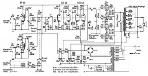
However, I have a very annoying oscillation with the pot labelled "H" in the schematic, which starts at around 20% and goes up proportional with flattening of the bottom half of the signal and adding ringing at approx. 5 times the frequency
I'm relatively new to tube design so I'm wondering whether one of you guys would have the patience to enlighten me about this oscillation phenomenon...
Thanks a lot for your patience
This is a future guitar amplifier and I'll use the second EF86 as an overdrive effect and replace "H" with a tone stack (would be for another thread if I require some help)
I scored a perfectly nice EL6411/01 amplifier on a local second hand sale site, and tested it beyond my expectations (50Vpp before clipping on a 130ohm load at 100V output setting, which would do around 75W)
However, I have a very annoying oscillation with the pot labelled "H" in the schematic, which starts at around 20% and goes up proportional with flattening of the bottom half of the signal and adding ringing at approx. 5 times the frequency
I'm relatively new to tube design so I'm wondering whether one of you guys would have the patience to enlighten me about this oscillation phenomenon...
Thanks a lot for your patience
This is a future guitar amplifier and I'll use the second EF86 as an overdrive effect and replace "H" with a tone stack (would be for another thread if I require some help)
Attachments
Last edited by a moderator:
"..very annoying oscillation with the pot labelled "H" in the schematic, which starts at around 20% and goes up proportional with flattening of the bottom half of the signal and adding ringing at approx. 5 times the frequency"
You might want to pump in a tone at the point while it's not oscillating and increase the tone input until full power. "Flattening" bottom indicated high distortion somewhere which is also the source of instability IMO, if not the output stage, check the bias, replaced the tubes, look for any clues.
You might want to pump in a tone at the point while it's not oscillating and increase the tone input until full power. "Flattening" bottom indicated high distortion somewhere which is also the source of instability IMO, if not the output stage, check the bias, replaced the tubes, look for any clues.
Last edited:
Have you removed the feedback and confirmed that all stages are operating correctly and that the output valves are all passing balanced idle current (which is likely going to require addition of cathode current sense resistors).
That amp wasn't designed with any frequency tailoring components within the feedback loop apart from the intrinsic roll-offs. You probably should do some step and square wave testing in to a resistive load, and then with added capacitance loading, then gauge inherent stability margin within the feedback loop. Making the feedback loop bulletproof stable is a good target, and may just require some output zobel loading, depending on your speaker loading.
You may want to add some extra protection - at least secondary HT fuses.
Sometimes the output transformer secondary taps can be separated - in which case you may be able to parallel up the 0-25V, and 25-50V, and give yourself a better coupled 16 ohm output winding.
thanks a lot guys
I'm not an audio expert but several things are easy to check
I guess next step is creating a small audio signal test thing (I have a couple µC dev boards which should be OK for this)
I'll still try the idle current and add a bias if needed, and the zobel network, as they are quick fixes
A small error from my part though, the output level was 50V amplitude so 100Vpp, I kept the figure in my head because my oscilloscope displays level from zero in its DMM mode
If I have to redesign the feedback loop, would you suggest another position for its input point if I reuse an EF86 as a preamp and the other as a tone stack?
Thanks a lot!
100Vpp is 35Vrms, which is 9-10W output across 130 ohm load.
A test signal is easy from a soundcard, or even better an android/iphone as they are isolated from AC mains. Find an app that gives easy tone/oscillator setup.
It is a vintage PA style amp, so quite a few technical issues would typically be encountered, as discussed in link:
http://dalmura.com.au/projects/Renovating PA amps.pdf
Thanks for the tips, I just wired some 1 ohm 3W resistors from each cathode to ground and I measure 1.5 to 1.6mV which seems to mean I have 1.5mA idle current, right?
Because of simplicity I kept the cathode and suppressor connected and tied the 1 ohm resistor from each to ground, does it sound right?
Maybe the screen and/or bias are incorrect? B+ measures 391V, EF86 anode is 212V, last ECC40 anode is 311V, screens are 195V and bias is -33V
I guess I would have to rewire it quite a bit as the grounding seems awful to me, but it is currently in a working state and I would rather make it OK before rewiring it, at least to have a known good state beforehands
I have removed the tone control pot, the voice filter and the mixer input to only keep the two EF86 input stages...
I'll do some more testing tomorrow evening if I can
I'll do some more testing tomorrow evening if I can
Yes keep the cathode and suppressor connected.
There could be a number of faults, so need to work through and check each section.
Screen supply should be half of B+, so that seems fine. I'd anticipate that preamp supply would be at least 100V less than B+, due to a few mA flowing through supply droppers. Loadline for ECC40 indicates 2mA for 2V bias with 250V supply. EF40 is grid leak biased, and triode connected, so can only measure anode voltage to determine bias position, but anode would likely site around 100V - it is very common for vintage grid leak resistors to wander a lot, and grid conduction to increase in the valve - so need to readjust.
Are you sure the 1.5mV reading on output valves is bona fide - it could be your meter, or there may not be any anode voltage connection through the OT.
There is some spec busting going on in this amp.
Except under pulse conditions, the max voltage is 250V for both anode and screen.
So with almost 400V on the anode, it makes sense to keep the screen at 200V and the idle current very low.
Now 1,5mA is too low. Could be old and worn out valves.
PS
The schematic shows that the 100V tap corresponds to a 250ohm load, the 130 ohm load resistor should be on the 70V tap.
oops my bad I was on the wrong output tap indeed
I'll retry this and measure again with all parameters clearer
this is an old amplifier, which was probably scavenged from and old factory by its previous owner and used as a turntable amp of some sort, so yes the valves are more than probably worn by age
what is good about this amp is the fact that all passives are pristine... I've ordered two pairs of CV2721 equivalents for testing...
OK, the (Dutch indeed) manual lists the voltages.
The EL81's should have between 297V and 315V on there anodes at idle.
Since you have a lot higher B+ you should check the mains voltage selector.
Idle current should be between 10 and 25mA and between 56 and 80mA at full power.
Bias voltage around -26V. If your mains is higher than the selector setting, this would be more negative as well, possibly explaining the low idle current.
I'll indeed double check everything again, but I'm pretty sure that the setting was on 240V as this is the first thing I checked...
Can this be caused by dry joints somewhere?
Can this be caused by dry joints somewhere?
Last edited:
OK I triple checked the voltage
Anode of the tubes are at 320V and bias at -30V
when applying a 1kHz sine at 50% volume with my 130 ohm load at the 70V setting I read 11.6mA for a pair, 6.6mA for one and 7mA for the last tube...
I guess there could be several issues, ranging from the ageing tubes to some bad screen or bias resistors
I'll wait for my new tubes to check with somehow equal characteristics as the previous owner(s) may well have changed a tube sometime
Well, I replaced by the NOS CV2721
Two tubes at 1mA idle, one at 1.2mA and the last at 0.8mA (still unbalanced)
When powering on and feeding a sinewave or music it squeals with a motorboat pattern... other voltages stay the same
Any clue?
Two tubes at 1mA idle, one at 1.2mA and the last at 0.8mA (still unbalanced)
When powering on and feeding a sinewave or music it squeals with a motorboat pattern... other voltages stay the same
Any clue?
It seems like the individual idle cathode DC current of each output valve is too low, and so they are operating close to class B fulltime. The manual indicates 10-25mA idle bias current, and about -26V bias voltage. So you would need to lower your present bias of -30V. R43 could be increased - that would reduce ripple/hum (compared to lowering R44).
The valves are rated for 8W anode dissipation, so perhaps if they can stably idle at 5W (ie. circa 15mA each) then that would be a good start. The higher idle current will lower the 320V back to nominal 300-310V level.
Best to remove feedback connection whilst setting up the correct operation of the stages. If there is still a 'squeal', then need to isolate amp stages to see what is influencing the output.
Last edited:
Those are nice and precise tips, thanks a lot!
In fact the squeal is not present anymore as I removed that pot and only left the two EF86 (schematic says EF40) input buffers, with a 15nF cap between buffer output volume pot and the triode stage input
The noise is now a motorboat at roughly 2 or 3 Hz superimposed to the signal and proportional to the volume, like a Whomp-whomp-whomp-whomp (I said squeal as I heard its HF component in the chassis at higher volumes, with my R load)
Do you think I should make a separate bias supply for each tube, as current is uneven? Maybe stabilizing the bias supply with a mosfet or other components would help?
I'll try to do this during the weekend
Do not stabilise the bias supply - that can be bad when mains voltage changes. Many do add an extra pot control for each valve, or for a 'side' of valves (the easier option) - just ensure that each pot is made failsafe, and can't accidently turn down the bias all the way, and has its output bypassed. The extra pot stage with its output bypass cap will further reduce any residual hum/ripple.
Motorboating is either from the use of one filter cap for many preamp tubes, or an old filter cap, or due to feedback unstable operation. So first remove the feedback to see if that is a concern. Effectively, four preamp stages are powered from the one supply node. R23, R25 could be powered from a new RC dropper taken from before R47 - that may minimise any interaction sufficiently.
Motorboating is either from the use of one filter cap for many preamp tubes, or an old filter cap, or due to feedback unstable operation. So first remove the feedback to see if that is a concern. Effectively, four preamp stages are powered from the one supply node. R23, R25 could be powered from a new RC dropper taken from before R47 - that may minimise any interaction sufficiently.
OK, I removed feedback and placed a 1k trimmer in the middle of the bias divider to adjust to 26V, which gives respectively 12, 19, 16 and 18 mA idle current
There is no more motorboating nor hissing, I've tested with my R load and will try it out with a speaker tomorrow to make other measurements and have a look at the sine on a scope
There is no more motorboating nor hissing, I've tested with my R load and will try it out with a speaker tomorrow to make other measurements and have a look at the sine on a scope
- Home
- Amplifiers
- Tubes / Valves
- Philips EL6411/01 amplifier