Yeah, but, to mungo would be mungoed.
To munge, munged.
Completely different verb. 😉
I suppose you could swap munged with distorted or altered, in this context.
To munge, munged.
Completely different verb. 😉
I suppose you could swap munged with distorted or altered, in this context.
Guys,
I don’t want to spoil your party but what’s needed on the I/V and output buffer is no op amp but a discrete circuit with NO FB.
😉
I don’t want to spoil your party but what’s needed on the I/V and output buffer is no op amp but a discrete circuit with NO FB.
😉
Pin 4 clock on TDA1541
Hi
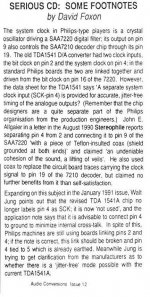
Some of you may be interested in the attached .
Its an extract from an article in Audio Conversions '92 (I think)
Edit..
The article carries on to say that The Audio Amateur 1/91 had an article by John Allgaier refering to clocking via pin4. Says that though early data sheets said the facility had been deleted but the Aug 1989 data sheet stated it was present.
Andy
Hi
Some of you may be interested in the attached .
Its an extract from an article in Audio Conversions '92 (I think)
Edit..
The article carries on to say that The Audio Amateur 1/91 had an article by John Allgaier refering to clocking via pin4. Says that though early data sheets said the facility had been deleted but the Aug 1989 data sheet stated it was present.
Andy
Attachments
Hi Andy, that's really interesting that!
Indeed in my cd94, pins 2 & 4 were tied together. I'll try connecting pin 4 direct to the decoder with coax, you never know 'til you try. If it's not better I'll ground it and see then.
Seeing as pins 2 & 4 were being fed the same signal, does pin 2 really need a divide cct?
Looks like there are a few combination's to try.
I'll report any findings here.
Cheers, Lee.
apassgear said:Guys,
I don’t want to spoil your party but what’s needed on the I/V and output buffer is no op amp but a discrete circuit with NO FB.
😉
My entire output is discrete! Burson for the I/V and Ray's DOS for the buffer stage.If you remove the feedback resistor from the I/V stage it just distorts??
Thomo said:Hi Andy, that's really interesting that!
Indeed in my cd94, pins 2 & 4 were tied together. I'll try connecting pin 4 direct to the decoder with coax, you never know 'til you try. If it's not better I'll ground it and see then.
Seeing as pins 2 & 4 were being fed the same signal, does pin 2 really need a divide cct?
Looks like there are a few combination's to try.
I'll report any findings here.
Cheers, Lee.
mmm.... I guess we'll be busy tomorrow then Lee!!! So does that mean Pin4 should have the system clock and 2 should have the /2 (based on what philpoole explained earlier)??
Reading it again, I'd say that the /2 (bitclock) should be on pin 2 and the system clock should be on pin 4 (if connected inside the chip) if not the Pin4 should be at ground.
Currently both pins are tied high (5v) which seems odd?
Also found this
http://www.audioasylum.com/audio/tweaks/messages/42670.html
Ian
You need the /2 to get the correct frequency for the bit clock.
On the non A, I think pin 4 needs to be the master clock, but for the TDA1541A this is not the case.
If I recall, first time I knocked up a DAC based on this chip, I had no luck with this pin 4 grounded, I had to attach to the bit clock to get any sound out.
Probably the best is to have the divide by 2 from the master clock and feed it to both - unless you have a non A chip.
Cheers,
Phil
On my cd304mk2 pin 4 is allready tied on gnd. Connect pin 4 to pin 9 of saa has probalbly the same effect of a 1/2 clock to dac from XO. Can try the pin 4 mod.
In my CD960 (marantz CD94) pin 2 and 4 are tied to CLBD on the Filter (saa7220/a) pin 16 with 3k9 to to the 5v rail.
The original DAC was a non A version. This is now replaced with an A ver double crown S2.
According to the datasheet for the A version,
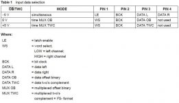
Table 1 Input data selection file attached as it didn't format properly!
As Andy stated in the article he attached, it looks like Pin 4 is not used in the A version unless you drive seperate L&R (simultanious) to the DAC.
So far as I can tell, for I2S you use the bottom line of the table (multiplexed Two's compliment).
So - pin2 def wants /2 for bitclock and according to the table, pin4 isn't used??
On the non A version, pin 4 can have a non "mudged" (clean!) system clock input which has got to be an improvement.
I'm going to try /2 on pin 2 then add system clock to pin4 and see what happens!
Andy's post states that in the Aug89 datasheet that pin4 was still sysclock!!
Ian
The original DAC was a non A version. This is now replaced with an A ver double crown S2.
According to the datasheet for the A version,
Table 1 Input data selection file attached as it didn't format properly!
As Andy stated in the article he attached, it looks like Pin 4 is not used in the A version unless you drive seperate L&R (simultanious) to the DAC.
So far as I can tell, for I2S you use the bottom line of the table (multiplexed Two's compliment).
So - pin2 def wants /2 for bitclock and according to the table, pin4 isn't used??
On the non A version, pin 4 can have a non "mudged" (clean!) system clock input which has got to be an improvement.
I'm going to try /2 on pin 2 then add system clock to pin4 and see what happens!
Andy's post states that in the Aug89 datasheet that pin4 was still sysclock!!
Ian
Attachments
Hi Ian,
Thanks, its all coming back to me now. I built my first DAC, and followed that table and it didn't work for me. Not until I saw someone elses schematic did I realise I should try tying pin 2 and 4 together. Then Bingo! It all worked.
Maybe this refers to an earlier revision of TDA1541A or something?
Its immaterial for me now as this pin is DATA R now because of the PMD100.
Cheers,
Phil
Busy morning!!!!
I started by adding a half decent regulator to the Trichord. This got me loads more detail (should have done this ages ago but been busy working on the output stage!) i had a good listen so that I could see what the /2 might do for me.
Next I fitted the /2. The clock input is fed from the Trichod and the supply from the same SPower giving the +5v to the DAC.
It looked straight forward to lift one of the R's (R550) and fit the /2 into the hole left. This gave me a short track supplying pins 2&4 on the DAC. I also removed the feed from the Decoder to these pins.
This gave me immediate gains, background detail is astounding. Its almost too clinical! lol
Been listening for an hour or so now and everything I put on, sounds bloody awesome.
1 thing I should point out, I also played with the I/V feedback R currently 1k8. I dropped as low as 600R to reduce the gain. The Bass just dissapeared! I've put it back to the original value now and will attenuate at the amp end of the leads.
Given that I've got a /2 feed onto pin4 at the mo, I'm assuming that its not connected as per the table I posted last night. If it was able to accept the sys clock, I would have expected problems with the /2 on it. Remembering the board was originally housing a non A version this could be why 2&4 are linked. Anyone disagree?
I think Lee's alread cut the link between 2&4 on his board so hopefully he'll have a go a putting the sys clock onto 4 and let us know (pretty please!) what happens......
Ian
Given that I've got a /2 feed onto pin4 at the mo, I'm assuming that its not connected as per the table I posted last night. If it was able to accept the sys clock, I would have expected problems with the /2 on it. Remembering the board was originally housing a non A version this could be why 2&4 are linked. Anyone disagree?
Disconnect pin 4 and see if it works?
Beware though, whatever happens, it'll be confusing 🙂
philpoole said:
Disconnect pin 4 and see if it works?
Beware though, whatever happens, it'll be confusing 🙂
I'm just waiting for Lee (Thomo) to test! He's already cut his track. If it makes no odds, I'll leave mine in tact!

You're not wrong about confusing!

Ian
Re: Where do I start ? .................. Photos
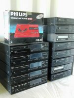
CD304s mk1 and mk2
CD104s
CD207 ... TDA1541 version of the CD100 - rare player
poynton said:
Let's see...........
I'l send you a photo when I get home, if you like...
Andy
SimontY said:
Some people settle for stamps!! Yes, please show us this impressive vintage stack!! 😀
........................
Simon
CD304s mk1 and mk2
CD104s
CD207 ... TDA1541 version of the CD100 - rare player
Attachments
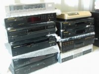

........... and there's more ................
There are more as well
B&O CD-X and CD50
plus some CD63s and CD273s
plus loads of spares....
I am in the process of sorting it all out and may sell some soon
Andy
There are more as well
B&O CD-X and CD50
plus some CD63s and CD273s
plus loads of spares....
I am in the process of sorting it all out and may sell some soon
Andy
Hi everyone.
Been messing about with these clock inputs etc. Pin 2 on the dac is supplied by a divide-by-two, from the main clock. This was an awesome mod, really enhancing the detail levels and dropping the noise-floor. Dynamics were massively improved. Dac pin 4 was still supplied as standard,, ie from the saa7220.
Next I removed all clock input from pin 4, the sound seemed to get more shut in, with less high level detail.
Then I supplied dac pin 4 from the divide circuit also, and it was an improvement. Highs were a touch cleaner.
Then I supplied pin 4 direct from the main clock, and this really brought it to life. Detail is up a big notch again, and the noise-floor really dropped away.
Hope i haven't bored anyone with my long-winded story, just thought you guys may be interested.
Tomorrow, I'll have a play with the decoupling caps at the dac. Which dac pins are most important please? I'll try those first.
Cheers, Lee.
- Home
- Source & Line
- Digital Source
- Philips CD650 mods