martin clark said:Re: HDAMs (regardless of whomsoevers take on it) - well after the CD63 thread where everyone reported it was worth omitting, it would seem bizarre to start adding the things here 😉
Interesting stuff, maybe I'll start with an LM317 then. And this noise thing should mean I get a big boost moving the I/V / output stage off the +/-15V that also feeds the DAC. I can't wait!
I think HDAM is good, the CD17KI has one and that sounds superb, in spite of those internal op-amps in the DAC chip. It's just that in te CD63 - at least - the HDAM was repeating part of the task of the op-amps. An extra stage.
I think Andy/Poynton was talking about replacing op-amps, not adding something extra in.
I'm sure the fact the CD85 (another 1541 player) sounds so shut-in is due to having something like 9 op-amps inside, even if they're not *all* in the signal path... There's less in the CD650 to keep the sound veiled. It's just somewhat noisy (hard, muffled sound) and when noise is removed from a rail the sound opens up in the classic veil-lifting style. Wonderful fun.
Simon
CDP description, Magnavox CDP650
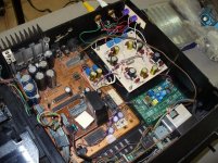
Center of pic is the main board, the lower 3 caps are Sanyo Oscons 150u, one on the DF the other two on the Dac, all three are on the Digital supply and are bypassed by 1.5u Tantalum caps (>That was may idiosyncratic touch… hehehe). The bypass to the analog supply on the DAC is a 330u FC cap bypassed (underneath) by a small conformal MKP.
To the center right of the main board, just on top of the DAC and the 330u bypass it can be seen a small piggy back board containing the plus current injection to the output of the DAC.
To the lower right corner the XO clock courtesy of Guido Tent, wish all my PCB looked as good as this one, just excellent work.
Decoupling caps on the DAC are 0.1u conformal MKP’s and on the most significant bit 2.2u Sanyo Oscon’s, all on the underneath of the board.
Big Ferrite rings around cables coming from the drive to the main board, also at the input of the raw analog supply to the CDP plus the small ones at the decoupling caps on the same board and some others on supplies at the main board. Plus some caps and ferrite at AC input.
Upper right is the analog section by yours truly the now famous (?, heheheh) OPA660. Each OPA has its own shunt reg at the rail through LM431’s. The actual OPA’s can not be seen on this pic cause they are underneath.
The last touches to this board were replacing some of the important resistors with PRP’s (red ones) and replacing MKP’s LPF with styrene on a double pole arrangement, first pole 2000p and second is 1000pf, don’t know exactly were I am on roll off corner, but sounds good to me.
Raw power supply to the analog board is external with 317/337 regs.
Finaly the Oscon output caps can be seen to the upper right corner of the pic (150u / 16V)
Attachments
martin clark said:
Re: HDAMs (regardless of whomsoevers take on it) - well after the CD63 thread where everyone reported it was worth omitting, it would seem bizarre to start adding the things here 😉
SimontY said:
I think HDAM is good, the CD17KI has one and that sounds superb, in spite of those internal op-amps in the DAC chip. It's just that in te CD63 - at least - the HDAM was repeating part of the task of the op-amps. An extra stage.
I think Andy/Poynton was talking about replacing op-amps, not adding something extra in.
As Simon says, in the CD63, the HDAM is used only as a buffer.
In other Marantz models ( the CD6000 comes to mind ) it is used as a discrete op-amp.
This is exactly what the Burson is.
It is possible to buy HDAM copies of Ebay. ( although from Audiotek168, who I wouldn't touch with a barge-pole! )
Which is why I wondeed if Brent would be producing some???
Andy
Interesting stuff, maybe I'll start with an LM317 then. And this noise thing should mean I get a big boost moving the I/V / output stage off the +/-15V that also feeds the DAC. I can't wait!
Alas, I don't have the luxury of seperate secondary windings for this, but the IV and DAC modules are individually regulated and decoupled.
I can never remember, this part of the TDA1541A is not well documented. Is the -15v for Dynamic Element Matching, the +5v for the digital circuitry, and the -5v for the analogue output stage? Makes guessing the ideal grounding a bit tricky. I shall trudge through that huge TDA1541 info thread again one day.
I'm making my DAC module dual at the moment, so its a good opportunity to review things like regulation and grounding. Unfortunately, for now, both DAC chips will share their power rails. I think a long term goal would be to rebuild the DAC board from scratch if the results are promising.
SimontY said:Good information chaps, lots for me to read then.
Here's a pic of my CD650 in standard form.
http://www.diyaudio.com/forums/attachment.php?s=&postid=1668108&stamp=1227658086
This reminds me of the Marantz CD65.
awpagan said:
.............
This reminds me of the Marantz CD65.
And many, many other Marantz / Philips models of the same period.......
Andy
SimontY said:I haven't yet mentioned a repeat of the DISC ERROR problem, but it reared it's ugly head when I finalised my work and closed up the player with all screws in place.
I found that if I pressed my meter's probe down hard on the mech connector it would read! So I thought maybe the connector was duff and followed tubee's helpful recommendation. I unclipped the cover of the connector and pulled each wire further through. I then clamped the connector back together and trimmed the excess... plugged it in and no joy!
I then realised I could make it work by applying pressure around that side of the main board. I took it out and re-soldered some areas and cleaned the PCB with a toothbrush to remove any metallic detritus.... no joy. I gave up in the end, for now, and left it with one screw missing - it plays like this. I must have a cracked track or lifted pad that I simply can't see. I'll investigate later
For now I want to listen more!
Simon
Simon, I have two CD1006 (=CD106) players (one with single crown
 ) Both were excellent running, but their transport didn't come out so I added some silicon grease etc.
The S1 version slid out but while working on the players both resorted to this DISC ERROR
 . I assume there is a transistor blown in the drive-motor logic: one board has molten plastic on the side of a TO-72 transitor.
  I will find out what happened, even though it is not a CD650, there might be some commons.
 alberti
Re: CDP description, Magnavox CDP650
Imo never use lytics for coupling 🙂
Better get some cheap Tube Light KP caps of 5.6uF or so, or motor starting caps. You will be surprised 😉
Oh before the beforementioned shunt PS with LM317/BD139 for SAA7210 and 7220 is powered, test it with a load resistor of about 30 ohms. If voltage is around 5V the try it on the chips.
apassgear said:Finaly the Oscon output caps can be seen to the upper right corner of the pic (150u / 16V)
Imo never use lytics for coupling 🙂
Better get some cheap Tube Light KP caps of 5.6uF or so, or motor starting caps. You will be surprised 😉
Oh before the beforementioned shunt PS with LM317/BD139 for SAA7210 and 7220 is powered, test it with a load resistor of about 30 ohms. If voltage is around 5V the try it on the chips.
dead tray on 650
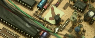
I made a picture of the main board with a blown transistor (mentioned on the board as item 6328).
The disk drive will not go out (even when aided by turning the main wheel at the left by hand); once out and once loaded with a disk, it does retract and play the disk (no disk error 🙂)
This transistor is the BC328 and connected to the M4804A Looks like it this BC328 is the fault. The collector goes to the drive connector (mid left on the board), emittor is earthed. I'll replace with a larger transistor.
But I am afraid the diskdrive will remain stuck with old grease etc.
Suggestion: better make it into a top drive?
alberti
Attachments
Re: Re: CDP description, Magnavox CDP650
I have tested lots of different caps at the output not the motor run type thou. MKP’s are good of course and will help to conceal some CDP noise problems; Oscons on the other hand will reveal most all. BTW, I have tested them against no cap.
tubee said:
Imo never use lytics for coupling 🙂
Better get some cheap Tube Light KP caps of 5.6uF or so, or motor starting caps. You will be surprised 😉
Oh before the beforementioned shunt PS with LM317/BD139 for SAA7210 and 7220 is powered, test it with a load resistor of about 30 ohms. If voltage is around 5V the try it on the chips.
I have tested lots of different caps at the output not the motor run type thou. MKP’s are good of course and will help to conceal some CDP noise problems; Oscons on the other hand will reveal most all. BTW, I have tested them against no cap.
Interesting to learn of this disc read error issue, though it sounds different to my problem (my drive and tray seem fine).
I've never heard of os-cons being used for signal coupling. I won't knock it till I've tried it, but I'm extremely satisfied with Mundforf Supremes.
Simon
I've never heard of os-cons being used for signal coupling. I won't knock it till I've tried it, but I'm extremely satisfied with Mundforf Supremes.
Simon
SimontY said:.............I've never heard of os-cons being used for signal coupling. ........
The newer "solid " electrolyte Os-Cons are supposed to be as good as Black Gates in some applications so maybe .....
Andy
poynton said:
The newer "solid " electrolyte Os-Cons are supposed to be as good as Black Gates in some applications so maybe .....
Andy
That's as may be, but BG N and BG AC (designed for speaker use) are easily surpassed by a good, basic MKP cap, more so by something top notch like a Supreme.
Simon
Of course, if you're feeling daring, you could omit the capacitor completely - but only if you are certain the preamp input will be happy with this.
(Disclaimer: Possibly bad advice - so ignore if you're not sure).
- but only if you are certain the preamp input will be happy with this.(Disclaimer: Possibly bad advice - so ignore if you're not sure).
SimontY said:
That's as may be, but BG N and BG AC (designed for speaker use) are easily surpassed by a good, basic MKP cap, more so by something top notch like a Supreme.
Simon
Yes. Imo the BG N type is overrated by a lot of people here.
[commercial mode] For Sale!! : 4 Black Gate Nx caps 47uF 16V [/commercial mode]
😀
tubee said:
Yes. Imo the BG N type is overrated by a lot of people here.
[commercial mode] For Sale!! : 4 Black Gate Nx caps 47uF 16V [/commercial mode]
😀
Handy parts to have around (for tight spaces), how much?
Simon
philpoole said:Of course, if you're feeling daring, you could omit the capacitor completely
(Disclaimer: Possibly bad advice - so ignore if you're not sure).
I ran mine like this for a while, but I got noise when turning the volume control, which I didn't want ideally.
Simon
Good call. Most pots become very noisy if there's any DC current running through the wiper connection (i.e., don't do it if it can be avoided at all)
- Home
- Source & Line
- Digital Source
- Philips CD650 mods