MidiMaze said:
No oops in this modification. The old op-amp I/V stage doesn't sound as good as the transistor stage 🙂
The oops referred to the fact that I had posted a question in error. I did not see the link on the picture.
Andy
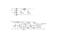
Can I use below clock layout to clock the 7000? I already have the Tent XO 8.4672MHz module. The idea is to divide the clock by two, same mod as MidiMaze. Some of the C-values are what I have lying around. Most of the layout is directly from Guido's site.
Thanks,
Jeroen
Thanks,
Jeroen
Attachments

JeroenR said:Hmm, values for two C's were wrong.
Thanks - what value for the beads ?
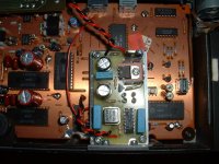
I had to take out the orginal EMI filter to fit in the transformer for the XO and drill some holes to mount the new EMI filter and euro power connector at the back. The pcb's are mounted with some thick and stiff wires that i have solderd to the original pcb so that it will hang underneath. The pcb at the back is solderd to the cich chasis.jives11 said:
Thanks MidiMaze
Nice site (and Pictures !) Wow you certainly managed to squeeze plenty into the chasis
Jonathan menthioned via the mail that the original caps must be at least 20 years old by now and that it might be worth replacing them. So i'am planning to take a look at that when i have some spare time.
jives11 said:
Thanks - what value for the beads ?
No idea. One of them came with the XO module, the other will be some generic one from a local electronic shop I'm afraid (perhaps combined with a little choke?).
two problems solved....
1. player now starts directly after turning on:
I replaced all caps on PSU, servo, cdm and tray pcb's. I used Nichicon low impedance for all except servo, there I used cheaper generic ones. All values a bit higher as I did not have the exact values. When I turn on the player I can play a CD directly, before it had to "warm" up half an hour.
2. tray closes completely:
I took of the tray mechanism and disassembled the traymotor. The wheels were cleaned and sanded lightly, at a local shop I bought a new, bit tighter, rubber band so replacing the old one. The tray now closes perfectly, before I had to help it with the last bit of the entry....
About ESD, I had all boards in my hands including the CDM board that is connected to the laser when I replaced all caps. There was a warning in one of the other forums about these old chips being sensitive to ESD. One could end up with a "greyish" sound..... My player is still working so phew.... But what about this "greyish" sound?? How do I recognise this? And is this possible? I can understand a chip failing after being fried but working a bit less good not. Any ideas???
Thanks,
Jeroen
JeroenR said:two problems solved....
About ESD, I had all boards in my hands including the CDM board that is connected to the laser when I replaced all caps. There was a warning in one of the other forums about these old chips being sensitive to ESD. One could end up with a "greyish" sound..... My player is still working so phew.... But what about this "greyish" sound?? How do I recognise this? And is this possible? I can understand a chip failing after being fried but working a bit less good not. Any ideas???
Thanks,
Jeroen
Well done. I have exactly the tray closing problem you describe. Sometimes it has the energy but mostly not and needs a little nudge.
I read that too, and like you I also handeled the boards while replacing caps and griplets. I'm sceptical that it would affect the sound in the way described.
I think the two caps that decouple the +/-12 v supplies are quite crtical. They serve a number of supplies as well as the opamps. I have some stargels at present but have some cerafines to put in, which I think are better in this role
JeroenR said:.....................About ESD, I had all boards in my hands including the CDM board that is connected to the laser when I replaced all caps. There was a warning in one of the other forums about these old chips being sensitive to ESD. One could end up with a "greyish" sound..... My player is still working so phew.... But what about this "greyish" sound?? How do I recognise this? And is this possible? I can understand a chip failing after being fried but working a bit less good not. Any ideas???..............
Touch wood, I have never fried a chip with ESD. [ 35+ years ]
But then I always touch the case to ensure I am at the same potential.
ESD will cause a chip to sound 'less good' if the discharge fries only part of the internal circuit eg if it is a symmetrical output op-amp and one half goes, it will still 'work' but obviously will not sound right.
Andy
I built a clock into the player, see photo. It has a dedicated powersupply. The previously posted layout was incorrect, I had pin 3 and 5 connected the wrong way around. Over the coming week I will listen to it a bit more but first impression: mwoh... not impressed so far. It might be it needs some time or a better I/V or make it NOS.
Attachments
JeroenR said:I built a clock into the player, see photo. It has a dedicated powersupply. The previously posted layout was incorrect, I had pin 3 and 5 connected the wrong way around. Over the coming week I will listen to it a bit more but first impression: mwoh... not impressed so far. It might be it needs some time or a better I/V or make it NOS.
Nice work. I also see you removed the DC blockers. You have some large (cerafine ?) caps on the 1540 supplies. what value are you using there ?
I have some small OSCONS here, but use the cerafines for the 2 opamp supplies (you have some black lyrtics here)
I started with pulling out the blocking caps. It made such a diff with my Marantz cd53. But... I do now have large plops when I change volume (stepped att.). Guess it is DC but as want to replace the opamps anyway I don't bother, did not even measure it...
The bigger caps next to the DACS are indeed cerafine. Well spotted!! The value is 220mu/35V. No science, just what I had on the shelve, the rest is cheaper Nichicon.
Yesterday I listened again and I had the feeling that things had improved after all. Voices (Christina Branco) sounded more present and music seemed to have more depth. But.... it was late, I spent a lot of time on the player, I was way past my first whiskey...
Next weekend I'm going to remove the SAA7030 or add a new I/V. Still a lot to gain I think and it's a fun machine to work with.
another approach is to run a dedicated supply to the SAA7030. I did this a few years ago to a CD65 and it made quite a big difference.
1541(A) NON-OS CD104
Hello,
I would like to add my modification of the 104 (actually performed at a CD-304 which has the same pcbs) to make it non-os with the venerable 1541(A) 16-bits DAC.
The 1541(A) supports the format that is present before the digital filter, that is the mode with seperate left and right data inputs. I am not shure, but the full 16 bits should be intact at this stage.
I made a tap of the decoderpins for the 4 digitalsignal lines (latch,BCK,Ldata,Rdata) and connected them to the 1541A with 100R resistors and some 7474 filpflops clocked on the bck (seprate pins on decoder). The psu of the 1541A is seperate since this is paramount to good sound for this DAC (+/-5V and -15V reference). The 1541 is well treated with polypropylene decouplingcapacitors and a DEM reclocker (see other threads in this forum) tapped and devided from the decoder clock-pins. The IV conversion is done with a home made copperwire resistor and tubed amplifier/buffer.
A possible future upgrade is to reduce the DAC noise level even further with a devider network that reduces the digital input voltage swing.
I haven't modified the 304 in any way (even no capacitorshrinkfoil stripping or powercable upgrade) yet it actually works and sounds superb.
As time goes by I get more and more sensitive to the digitalness of most digitally filtered designs and lack of speed/drive and substance in most CMOS based DACS (1543 for a good exception).
Please there is no need explaining the need for oversampling or the use of elaborate analog filtering, the technical superiority of ss IV converters/buffers and the like. I am fully aware of the shortcomings of this design, yet I subjectively find this combination (104+1541 in NON-OS) the most musically satisfying digital combination I have ever heard.
I hope this provides for some new inspiration!
regards, Coen
jives11 said:another approach is to run a dedicated supply to the SAA7030. I did this a few years ago to a CD65 and it made quite a big difference.
Thnaks, but I want to try the NOS tweak, so removing the 7030.
Re: 1541(A) NON-OS CD104
Why the more complicated route with the 1541? Is the 1540 that bad? Or was it just the chalange?
Absolutely. But being a man I'm more turned on by photo's. 😉
Co& said:Hello,
I would like to add my modification of the 104 (actually performed at a CD-304 which has the same pcbs) to make it non-os with the venerable 1541(A) 16-bits DAC.
Why the more complicated route with the 1541? Is the 1540 that bad? Or was it just the chalange?
I hope this provides for some new inspiration!
regards, Coen [/B]
Absolutely. But being a man I'm more turned on by photo's. 😉
Re: 1h???
Uhhh..... 1 is indeed 1000m.
Why do you ask. 😀
Serious, I have no clue. I asked for 400mH because that is what I remember Guido reply once in a post. I got this one. (you can see it in the photo in my post on 20-2 in this thread, it is the small black dot in the middle) They told me it is 1H. As I do not have direct access to a decent parts-shop where I live I just used it. Next time I open the hood of the player I will check the label. My electronics experience is limited so I do not (yet) recognize silly values.
What would suggest as a good value?
Thanks,
Jeroen
Elso Kwak said:
1H??????
(That is 1000 mH)
😕
Uhhh..... 1 is indeed 1000m.
Why do you ask. 😀
Serious, I have no clue. I asked for 400mH because that is what I remember Guido reply once in a post. I got this one. (you can see it in the photo in my post on 20-2 in this thread, it is the small black dot in the middle) They told me it is 1H. As I do not have direct access to a decent parts-shop where I live I just used it. Next time I open the hood of the player I will check the label. My electronics experience is limited so I do not (yet) recognize silly values.
What would suggest as a good value?
Thanks,
Jeroen
- Home
- Source & Line
- Digital Source
- Philips CD104 tweaks