?
A college of mine, when I was repair-tech, who did many Philips CDPs as his shop sold them a lot, told me resoldering was adequate.
😎
poynton said:
Hi.
The only way to repair this problem is to drill out each griplet and solder a wire through from top to bottom.
Resoldering will not cure the problem!!
Andy
A college of mine, when I was repair-tech, who did many Philips CDPs as his shop sold them a lot, told me resoldering was adequate.
😎
I have a few tested servo boards to fit into CD104, 204, 304, 304mkII, Grundig CD7550, and maybe others.
This fixes 99% of all problems.
15 € incl. registered shipping inside Europe, 20 € rest of the World.
This fixes 99% of all problems.
15 € incl. registered shipping inside Europe, 20 € rest of the World.
Re: ?
Hi.
Resoldering would be adequate IF the plate-through was always 100%. Wiring through the hole makes sure!
Andy
Elso Kwak said:
A college of mine, when I was repair-tech, who did many Philips CDPs as his shop sold them a lot, told me resoldering was adequate.
😎
Hi.
Resoldering would be adequate IF the plate-through was always 100%. Wiring through the hole makes sure!
Andy
Re: Re: ?
As far as I know the wire is already through the hole
poynton said:
Hi.
Resoldering would be adequate IF the plate-through was always 100%. Wiring through the hole makes sure!
Andy
As far as I know the wire is already through the hole
How many problematic joints are there on servo board ?
I found two or three , and others are allready factory wired.
Audio board has no such joints , all looks like wired ones , like shortcuts from trace side (two of sloder joints) to ground side.
I found two or three , and others are allready factory wired.
Audio board has no such joints , all looks like wired ones , like shortcuts from trace side (two of sloder joints) to ground side.
Gasho said:How many problematic joints are there on servo board ?
I found two or three , and others are allready factory wired.
Audio board has no such joints , all looks like wired ones , like shortcuts from trace side (two of sloder joints) to ground side.
thats right, there are only two griplet holes in the servoc board plus a number of wire links and axial caps with large solder 'blobs' at the end. The links and caps I resoldered (sucked the old solder and resoldered) the 2 griplets I desoldered untill I could see the end of the griplet. I drilled a hole through the middle of the griplet, desoldered again, then ran a small lenth of tinned wire through the hole and resoldered on either side. NOTE The griplet is still there, I found them too hard to remove without removing the tracks on the non-copper side.
The audio (decoder) has approx 10 griplet connections through plus a couple of the cap/wire link blobs.
Still no TOC and music from my player.
I run tests with oscilloscope but didn´t see any errors.
Signal goes from transport to DAC board and to decoder board.
I don,t know how looks a good signal but it is present so that indicate that laser pick up is reading something from CD when I press play button.
I will run some tests again.
Maybe the quartz that feeds microcontroler is running out from correct frequency , maybe spindle motor don´t have correct speed.....
Any sugestions?
I have service manuar of CD104 but there is a lot of difference from 304 mk2.
Must check all solder and ground points again .
looking at the decoder schematic, I notice that some of the wire links distribute power to various chips. I wonder if these links could be better replaced with ferrites or small value inductors ? I'm guessing that the supplies are modulated by the clock freq so does anybody
1) Believe this is a good idea
2) suggest a value of inductor/ferrite suitable to attenuate noise in the 4Mhz region
1) Believe this is a good idea
2) suggest a value of inductor/ferrite suitable to attenuate noise in the 4Mhz region
Attachments
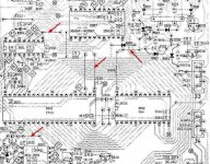
jives11 said:looking at the decoder schematic, I notice that some of the wire links distribute power to various chips. I wonder if these links could be better replaced with ferrites or small value inductors ? I'm guessing that the supplies are modulated by the clock freq so does anybody
1) Believe this is a good idea
2) suggest a value of inductor/ferrite suitable to attenuate noise in the 4Mhz region
Hi,
Taking your 3 jumpers from the top.
1. The one next to diode 6561 is connected to a 47uH choke 5505 before reaching the ram.
2. This could be replaced by a choke - all the rest are 47uH. Decoupling on this chip is done by sm cap 2538 - the tracks for this are rather long. I would add a further cap soldered to the ic pins.
3, The last link is also decoupled 'remotely'. I think an extra 47uH or bead plus extra decoupling cap closer to the ic would not go amiss.
Andy
poynton said:
Hi,
Taking your 3 jumpers from the top.
1. The one next to diode 6561 is connected to a 47uH choke 5505 before reaching the ram.
2. This could be replaced by a choke - all the rest are 47uH. Decoupling on this chip is done by sm cap 2538 - the tracks for this are rather long. I would add a further cap soldered to the ic pins.
3, The last link is also decoupled 'remotely'. I think an extra 47uH or bead plus extra decoupling cap closer to the ic would not go amiss.
Andy
Thanks Andy, any thoughts on the fourth link 🙂
I also noticed that the Right channel has no local ceramic on the +12v supply. The left Channel does and the -12v does. The +12v gets delivered all over the baord as well as the NE5532's. This supply is decoupled by 2627 (22uF). I use a starget here of 47uF but wonder if an alternative cap would be better given the dual role of supplying both analogue and digital supplies.
jives11 said:
Thanks Andy, any thoughts on the fourth link 🙂
I also noticed that the Right channel has no local ceramic on the +12v supply. The left Channel does and the -12v does. The +12v gets delivered all over the baord as well as the NE5532's. This supply is decoupled by 2627 (22uF). I use a starget here of 47uF but wonder if an alternative cap would be better given the dual role of supplying both analogue and digital supplies.
Hi,
OOPS - missed the one by that chip !!.
I would say replace with a 47uH choke and add a local bypass cap.
THINKS ... I have read somewhere that the filter chip should be fed with its own supply direct or was that the SAA7220 ??
All the chips should be decoupled as close as possible to the chip +/- as possible ie. very short leads to the pins of the chip.
Andy
Another clone?
Hi.
I have just returned home, having braved the ice and snow here in N. Wales. While out, I came across a car boot sale - yes there are some hardy souls out there or should that be idiots?
Anyway, I picked up a Marantz CD74 for £3.00 !!
Works perfectly (apart from having had a bang on the front panel).
It looks like Marantz clone for a Philips 304 - cdm1, alloy chassis, same boards etc.
But the PSU is bigger and there is an extra Tx feeding the Display board.
Loads of space for modding !!
Anyone have any info??
Andy
One pretty good tweak for CDM1-2 based cdp is change of NE5514 quad OP for faster one like MC33079 or even better ones.
It is the first signal gain stage after photodiodes in laser pick up unit.
It is located on CDMs pcb integrated with mech.
It is the first signal gain stage after photodiodes in laser pick up unit.
It is located on CDMs pcb integrated with mech.
Re: Another clone?
Unfortunately, the chassis was twisted and I could not straighten it. So I now have a spare cdm-1 (which is the quietest I have ever heard ) and boards for the CD74 - Anyone need spares?
Andy
poynton said:..................I picked up a Marantz CD74 for £3.00 !!
Works perfectly (apart from having had a bang on the front panel)................
Unfortunately, the chassis was twisted and I could not straighten it. So I now have a spare cdm-1 (which is the quietest I have ever heard ) and boards for the CD74 - Anyone need spares?
Andy
Poynton: build a new case around it, and make a toploader or something like Roberto's very  design:
http://www.diyaudio.com/forums/showthread.php?s=&threadid=73089
design: http://www.diyaudio.com/forums/showthread.php?s=&threadid=73089
tubee said:make a toploader or something like Roberto's very
Ah...now thats something !!! 😀
I have also modified a CD104, an excelent player in my oppinion. I use it to feed my headphone amp and Sennheiser HD-580.
The original clock has been replaced by a Tent-Labs version and the original I/V stage had been removed and replaced by a transisor version.
CD-104 modifications
The original clock has been replaced by a Tent-Labs version and the original I/V stage had been removed and replaced by a transisor version.
CD-104 modifications
MidiMaze said:.......... the original I/V stage had been removed and replaced by a transisor version.............
oops
Thanks MidiMazeMidiMaze said:I have also modified a CD104, an excelent player in my oppinion. I use it to feed my headphone amp and Sennheiser HD-580.
The original clock has been replaced by a Tent-Labs version and the original I/V stage had been removed and replaced by a transisor version.
CD-104 modifications
Nice site (and Pictures !) Wow you certainly managed to squeeze plenty into the chasis
No oops in this modification. The old op-amp I/V stage doesn't sound as good as the transistor stage 🙂poynton said:
oops
- Home
- Source & Line
- Digital Source
- Philips CD104 tweaks