^ It could be the relay. Check the contacts are not stuck closed and make sure there is a delay before the relay operates.
The reed switches them selves can be removed and exchanged. But you have to be carefull with the glass from the reed switch.
You need to bend the legs after insertion in de coils and not brake the glass.
You need to bend the legs after insertion in de coils and not brake the glass.
The draw is intermittent on my unit, belt has been changed, I've read somewhere the tray switch could need cleaning, where would I locate this and how to clean it?
Hello friends, so far everything smooth by the resurrection of cd104 and his friend 304.
Set laser supply to 550mV with a normal pressed CD.
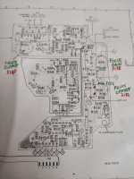
I like to do things spot on, so I'm wondering what for are the two other trim pots "focus gain s(hould be focus bandwidth)" and focus offset.
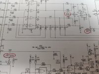
From what I've drawn from the schematic, focus offset should have 0V difference between pins 2 and 3 of 6107 uA741.
But focus gain?
Has it an influence on the RF Eye pattern? Or this should be set to Vpp=1.2V only through the laser output pot?
Yes, I read Mike Leach's article, but he doesn't delve in these detail.
Thank you.
Set laser supply to 550mV with a normal pressed CD.
I like to do things spot on, so I'm wondering what for are the two other trim pots "focus gain s(hould be focus bandwidth)" and focus offset.
From what I've drawn from the schematic, focus offset should have 0V difference between pins 2 and 3 of 6107 uA741.
But focus gain?
Has it an influence on the RF Eye pattern? Or this should be set to Vpp=1.2V only through the laser output pot?
Yes, I read Mike Leach's article, but he doesn't delve in these detail.
Thank you.
Attachments
I also want to know the purpose and adjustment method of Focus Offset. Since the servo is a closed loop, the voltage difference on pin 2 and 3 on the uA741 is always zero. Perhaps it should be adjusted by breaking the loop. I could not find any description anywhere.
As for the Focus Gain, it is described in the service manual of the CD player. A certain frequency is to be fed to a point, and the Lissajous pattern should be monitored on an oscilloscope, and the FG should be set to 90° phase shift. I suppose it adjusts the damping of the focus loop. It is not a super critical adjustment, the factory setting is usually OK.
As for the Focus Gain, it is described in the service manual of the CD player. A certain frequency is to be fed to a point, and the Lissajous pattern should be monitored on an oscilloscope, and the FG should be set to 90° phase shift. I suppose it adjusts the damping of the focus loop. It is not a super critical adjustment, the factory setting is usually OK.

Actually the focus offset can vary, have a look at the schematic. Today I adjusted that pot, it had drifted to 200mV...
How does it interact with the Torx screw that adjusts the turntable height? I think the ultimate goal is that all 4 photodiodes should get the same amount of light, and put out the same amount of current. But it can achieved by adjusting the table height or turning the FO variable resistor. Which comes first?
No, I meant the pot on the laser PCB (focus offset)
To do what you mean (don't know whether is focus offset as well), you've to measure a pin in the servo PCB connector, and then set the height to zero that reading.
To do what you mean (don't know whether is focus offset as well), you've to measure a pin in the servo PCB connector, and then set the height to zero that reading.
I always say this... Philips test procedures are often bizarre and convoluted 🙂
The Focus Offset R3132 looks to trim any electrical imbalance in the photo diode array. I can't spot any obvious reference to adjusting the preset and so I would look with a scope set accurately to show DC at the output of the 741 and see what happens between stop mode and play with a good disc.
It looks to me like you adjust the DC shift to be zero but try it with the scope. The 741 will always seem to have essentially zero volts between the two inputs (because it is configured normally with negative feedback via R3125) but the opamp output can vary depending on the preset and the offset.
Focus Gain isn't normally very critical, to low and its prone to lose focus easily and to high and the focus coil can be noisy as the system approaches instability. Again I would dangle a scope on the main focus coil driver stage and look at the output to the focus coil which should be a relatively low frequency fluctuation superimposed with a DC offset (the DC needed to move the lens to the correct position). Turn the gain up and look for any signs of obvious instability (likely showing as HF becoming superimposed on the focus output signal) and then just back the gain off a little from that point.
Hey Karl,
Yes, that's how I understood it. The focus point should be balanced electrically and the mechanical adjustment returns the balance to zero while playing a disc. We had some that the lens assembly sagged and they would read when adjusted correctly, or if you compensated they would read but wouldn't play.
Aligning he swing arm. Forget it. Revox decided it was factory only, they loaned me the glass disc and I tried as well. Not worth the effort for the time it took. I agreed, factory alignment only. That glass disc was stupid expensive at the time (as was everything else Philips for test materials).
Hi Michelag,
You can get into more trouble than you can imagine adjusting this stuff if you are not specifically trained. I was trained at Philips and at Revox. Adjustment controls are the very last things you should touch with a CD player. You should see the mess people make of tuners! I've seen plenty of really messed up CD players and that is as long as they don't burn out the laser diode.
Oh ... for sure!I always say this... Philips test procedures are often bizarre and convoluted.
Yes, that's how I understood it. The focus point should be balanced electrically and the mechanical adjustment returns the balance to zero while playing a disc. We had some that the lens assembly sagged and they would read when adjusted correctly, or if you compensated they would read but wouldn't play.
Aligning he swing arm. Forget it. Revox decided it was factory only, they loaned me the glass disc and I tried as well. Not worth the effort for the time it took. I agreed, factory alignment only. That glass disc was stupid expensive at the time (as was everything else Philips for test materials).
Hi Michelag,
You can get into more trouble than you can imagine adjusting this stuff if you are not specifically trained. I was trained at Philips and at Revox. Adjustment controls are the very last things you should touch with a CD player. You should see the mess people make of tuners! I've seen plenty of really messed up CD players and that is as long as they don't burn out the laser diode.
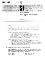
Some Service information in German about focus offset 😎
Google translate
---------
1. Adjustment of focus offset
The adjustment of the "Focus Offset" adjuster on the preamplifier and laser print can - if necessary - be carried out using either of two different methods:
a.) with supply of a measurement signal
b.) in the player's play function
2. Addition to the spare parts list
The sockets A 10 and A 11 on the preamplifier and laser print (connectors for the flexprints from the light pen) are listed as spare parts:
A 10 - 6 pin 4822 267 504 12
A 11 - 8-pin 4822 267 504 13
Google translate
---------
1. Adjustment of focus offset
The adjustment of the "Focus Offset" adjuster on the preamplifier and laser print can - if necessary - be carried out using either of two different methods:
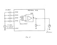
a.) with supply of a measurement signal
- Make connections according to Fig. 1.
- Set the voltages at pin 6/IC 6107 to minimum (< 100 mV) with “Focus Offset”.
b.) in the player's play function
- Error-free plate - e.g. B. Test plate 5 (Order-
- With "Focus-offset" The HF signal on MP 65 ("eyepattern") to a value > 500 mV (measure with AC millivoltmeter).
2. Addition to the spare parts list
The sockets A 10 and A 11 on the preamplifier and laser print (connectors for the flexprints from the light pen) are listed as spare parts:
A 10 - 6 pin 4822 267 504 12
A 11 - 8-pin 4822 267 504 13
Attachments
Last edited:
Yes, notice they didn't mention the mechanical offset adjust. Their huge assumption is that this has not been disturbed, or wear has not occurred (or suspension has sagged).
In service, you never make assumptions unless you have good evidence they will be true. That and you never, ever perform adjustments of any kind if you do not have the training, tools and equipment to do so.
In service, you never make assumptions unless you have good evidence they will be true. That and you never, ever perform adjustments of any kind if you do not have the training, tools and equipment to do so.
I didn't make the non over sampling mod to get back to 14 bits. I read pros and cons from both respectable people. I am scratching my head, any comments ?
They did the best they could with 14 bit at the time. My Nakamichi OMS-7 is the same.
Honestly, 16 bit is better - no contest. Oversampling is a huge gain in quality. One reason is that you don't need such a high order filter. People who do not institute the filter are totally irresponsible and have zero understanding of how this stuff works.
With a lower order filter, a lot more of the sampling frequency escapes out into your system. You can't hear 44.1 KHz, but it can interfere with the electronics, create distortion as your active circuits have less feedback higher in frequency. WOrst case - out to your speakers it goes and straight to your tweeters where they attempt to reproduce that signal you can't hear.
We do the same with FM stereo tuners. We have to quickly filter out the 9% modulated 19 KHz pilot tone. Otherwise it does the same thing. With CD, the NO filter is set to about 22 KHz (guess why?). With digital the sampling frequency is full bore folks.
DSP and filters that oversample and interpolate to 92+ KHz and 20 + bits do perform better, and they sound better given the audio and filtering is done properly. I've serviced CD players and DACS since the beginning and there are very good reasons why they increased bit depth and sampling frequencies. The NOS crowd hasn't a clue, and are dangerously misinformed.
Last edited:
Just simply read up on sample rates and digital filtering. Not even the correct terms are used in that link. Read from DAC manufacturer app notes (not white papers). May as well get the right information from real engineers instead of what people think they know.
- Home
- Source & Line
- Digital Source
- Philips CD104 tweaks