Hello Bassivus,
Your approach seems correct! Remove the de-emphasis circuit with all associated parts including the BC858B and definitely get rid of everything after C2366 and C2367. Get your audio signal after the analog filter at leg 7 of the op-amp or before at leg 1 to use just the first half of the op-amp.
Get some decent output decoupling caps, between 2,2uF and 4,7uF will do nicely if the input impedance of your preamp is higher than 30kΩ. I use Wima MKP10 2,2uF as they fit fine into the casing and are very cost efficient. But get them with a voltage rating of 400VDC/250VAC or BELOW. Even better, but pricier, are Mundorf Mcap ZN or Audyn Cap KP/SN from Intertechnik. You can even add a regulator and use it for a complete offset correction to get rid of the decoupling caps completely.
If you don’t use the headphone circuit, you should de-install that as well. And de-solder everything that has to do with the variable output (the NJM4560D and its circuit)! If you have removed everything that is not necessary for the basic function of the Grundig, you will find that you now have an unused 7805 (I think it was the one without contact to the heat sink). Use that regulator to supply the SAA7220 directly or for the offset correction (with some additional circuit).
Solder in some sockets and op-amps like OPA2134, THS4032, LM4562 or the like with about 100uF of Panasonic FC (cheap) or Elna Silmic (best) as local decoupling and a 100nF film/foil cap between leg 4 and leg 8 (directly soldered to the legs of the socket).
And change all old electrolytic caps in the power supply, on the CDM2 or CDM4 (the Grundig uses both versions) and on the servo ICs for Panasonic FCs or equally low ESR caps. For the digital ICs (TDA1541, SAA7220 etc.), Sanyo Os-cons are best. Use a reasonable size; don’t exchange a 47uF cap with a 2200uF cap as I have read elsewhere. Usually 100uF will do in that case.
In the end, the quality of the circuit (and an intelligent modification) is far more important than certain audiophile caps or silver wire or snake oil. Spending your money on separate regulators for the ICs or good op-amps or even a valve output is miles more cost efficient than any Black Gate or Mundorf Silver/Gold or VCap TFTF alone.
Best regards,
StefanAC
Hello Andreas,
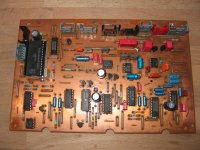
I need you to confirm the size of C2514 on the decoder board at pin 22 of the SAA7210. Is it 3,3uF or 33uF!?! In the manual it is 3,3uF, but I thought I read 33uF on the cap itself. Someone re-soldered the griplets before I bought the player the writing on the cap is barely readable. This might be the cause for the constantly spinning turntable motor. I had a second look at it after your advice to watch after 33-1 to 34-4!
Best regards,
Stefan AC
100% agree with stefanac. Steal the signal at pin 1 after the first half of op-amp even if you liked to use tube buffer. Don't use a simple resisitor for I/U. I experimented with tubes there too. That does not spend is worth. Take the THS4032 and time and money saved....planning in installing tube out via resistor I/V,
Original there is a 3,3µF 50V nichicon not axial. I use there 3 x 1µF 40V tantal. Once i tryed there a 100µF i get problems....confirm the size of C2514
... only need 6 by 6 holes on a standard PCB for each regulator.
Looks very good. Nice mounting position at the heatsink. Have you a pic from the other side?
Hello Andreas,
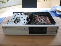
Unfortunately I forgot to make pictures of the supply board the last time I had the CD204 dissembled. But I will make some the next time – there is always something to improve 😉.
I just changed the C2514 on the decoder board – out came the 100uF Panasonic FC and in came a 3,3uF Wima MKS2. The Wima fits perfectly in that place, but – the turntable motor still keeps spinning .
.
Best regards,
StefanAC
Unfortunately I forgot to make pictures of the supply board the last time I had the CD204 dissembled. But I will make some the next time – there is always something to improve 😉.
I just changed the C2514 on the decoder board – out came the 100uF Panasonic FC and in came a 3,3uF Wima MKS2. The Wima fits perfectly in that place, but – the turntable motor still keeps spinning
.Best regards,
StefanAC
Hello Andreas,
Actually, I can’t tell you the direction in which the turntable motor was spinning. After my modification yesterday and testing afterwards, I was so peeved at the CD204 MKII that I placed it out of sight and was planning not to do anything with it for the next months. But due to your question, I took it from its shelf, manually inserted a CD to better see the spinning direction, powered it up and – the turntable motor didn’t turn. I pressed the start button and the CDM1 immediately started to read the CD. I tried every button on the front and the CD204 MKII did what it was supposed to do. I connected it to my music system and the sound was fine. Excellent 😀! Maybe it is time now to start a new thread about the self healing properties of old Philips CD-players 🙄?!
By the way, why do you use three tantalums as a substitute for C2514? That definitely isn’t plug and play! And a 3,3uF Wima MKS2 is only half a Euro at Reichelt…
I am in the process of changing all tantalums as well as all small size and bi-polar electrolytic capacitors in my CD204 MKII to film and foil type caps of up to 10uF. That should improve the reliability and is only about 5€ on these old Philips machines.
Best regards,
StefanAC
Hello Bassivus,
A friend of mine has two CD-9000 (one playing and one for parts) but no service manual. Is it possible for you to mail me a pdf of yours? The mail address is stefan.runge AT gmx.de. Thanks a lot!
Best regards,
StefanAC
A friend of mine has two CD-9000 (one playing and one for parts) but no service manual. Is it possible for you to mail me a pdf of yours? The mail address is stefan.runge AT gmx.de. Thanks a lot!
Best regards,
StefanAC
Hello Bassivus,
Your approach seems correct! Remove the de-emphasis circuit with all associated parts including the BC858B and definitely get rid of everything after C2366 and C2367. Get your audio signal after the analog filter at leg 7 of the op-amp or before at leg 1 to use just the first half of the op-amp.
...
Thanks very much! I did not want to go in the details so I don't slip in off topic
 so I asked just for deem, but my player is already pretty modded: http://www.diyaudio.com/forums/digital-source/111020-rejuvenating-moding-grundig-cd-9000-a.html
 I also have one more "donor" player for parts...😀
I have ordered this buffer to try with player:Tube Module DIY Kit for DAC, buffer with HV transformer bei eBay.de: Amplifiers (endet 24.10.09 01:49:35 MESZ)
I think I'll take the advice and take signal after op I/V so I can have opamp out active together with tube out
P.S. Stefan check the mail😉
Hello Bassivus,
Thank you very much for the manual 🙂! My friend already did a few small mods like the ones I mentioned to you but was hesitant to go further without a manual. And after my experiences with the CD304 MKII (differs from a CD104/304 in more than the decoder board), I can fully understand him!
After having a look into your CD-9000 thread, I realize that you already implemented most of what I wrote. And more! On first glance, I feared you used the Panasonic FC as output decoupling caps (C2356 and C2367), but than the Mundorfs came into view. For a signal stealing point after the first half of the op-amp, I would try C2352 and C2353.
Otherwise, take care of the SP/DIF trace and get rid of the transformer next to the op-amps. And use mica sheets for the voltage regulators to avoid ground loops.
The tube output seems interesting, but I would go with just a THS4032 as nanocamp already said. Or at least use the first half of the op-amp for I/U conversion. The TDA1541 does not like a resistive load! If you still want to omit the op-amp, stay below 80 ohms for the resistor. The lower, the better!
By the way, do you know where to get a Grundig CD-903 / CD-8400 MKII manual? These player look very promising as the use only through hole components.
Best regards,
StefanAC
I know that well, one hour to walk in the forest and you come back with new possibilities to try... placed it out of sight and was planning not to do anything with it for the next months.

Congratulations! Seemed that we both finsiched same time. I will try the USB later since I work on an active-crossover prefer must. I hope you will present the finished projekt here with many pictures. I will do later the same. Than you can see my ALF (anti listening fatigue) - the switchable fur purchase for the loudspeakers... pressed the start button and the CDM1 immediately started to read the CD.
I love them and i have them. I use them even for output decoupling with a non polar electrolyte ...... why do you use three tantalums as a substitute ...
You want to do or you already did it?... I have ordered this buffer
By the way, do you know where to get a Grundig CD-903 / CD-8400 MKII manual? These player look very promising as the use only through hole components.
Best regards,
StefanAC
Did you scroll all the way down in manual? 🙂
You want to do or you already did it?
Actually it has already arrived but since I ordered it without trafo I haven't tried it yet ... have to consolidate budget to get one...
Hello Andreas,
I will post additional pictures of my CD204 MKII when the project is finished. There are still some tantalum caps (AARRGGG!!!) on the servo board that need to be exchanged, the de-emphasis circuit isn’t removed yet and the output decoupling caps are still Wima MKS2 while some MKP10 are already waiting. And finally, I need to build some dedicated power supplies for the op-amps, the DAC and the filter as I did for my CD204.
Best regards,
StefanAC
Attachments
Hello Bassivus,
I did scroll down. But the manual doesn’t cover the CD-903 / CD-8400 MKII variants. As far as I know, these were Grundigs own development and did feature proprietary PCBs without SMD components. I think they were even mentioned on the Lampizator website. Internal views can be found here:
http://www.dcaudio.pl/toiowo.htm
Best regards,
StefanAC
I have a CD880 with separate IV/buffering PCB with special opamps and analog/deepmhasis with better parts (styrene) Discovered that only 1 CD uses deemphase, a test CD from german magizine "Audio" As far as i am concearned the deemphase circuit can simply removed then.
I am not sure, but on some or other reason i think/guess that an tube stage is only worth the effort when you do it very thourough. So with proper (shunt) and choked regulated HTPS, regged heating PS, and the best value and make I/V resistors. Or simply choose the THS 😎
I could be mistaken, but i again guess the only way to get better sound also from a Nonos player is with a decent output transformer. This adds nice filtering and decouples the dac from your amp input.
A discrete output stage seems still another attempt worth. Someone told me to give the BURSON a try.
An externally hosted image should be here but it was not working when we last tested it.
Did somebody already make this Burson op-amps with experiences?
Or with this much cheaper Audio-gd Discrete OPA?
Or with fetishizator?
Hi Andreas,
I think Audio-gd's OPA Moon gives more 2nd harmonic distortion than OPA Sun.
I can't find mutch information about OPA Sun.
By the way a detail about the distortion of OPA Earth and OPA Moon can be found from the link below.
-http://www.sg-acoustics.ch/analogue_audio/ic_opamps/pdf/opamp_distortion.pdf
OpAmpsBy the way a detail about the distortion of OPA Earth and OPA Moon can be found from the link below.
http://www.sg-acoustics.ch/analogue_audio/ic_opamps/pdf/opamp_distortion.pdf
That is great piece of work there but measurements are only one thing for audiophiles. I am reliably SG could much experience-collect and I will give a try to his SGA-SOA-1 Simple Discrete Operation Amplifier.
Bassivus i agree with that. In particular because I bought already different products of China. Except the I/U resistor. There you should take the THS in any case.I am not sure, but on some or other reason i think/guess that an tube stage is only worth the effort when you do it very thourough. So with proper (shunt) and choked regulated HTPS, regged heating PS, and the best value and make I/V resistors.
I could be mistaken, but i again guess the only way to get better sound also from a Nonos player is with a decent output transformer. This adds nice filtering and decouples the dac from your amp input.
Because the dual burson behind the TDA1541 non A failed completely, I had switched my laser sword on and had pierced him. From this rose a hybrid-amp with dip8 is content.
Attachments

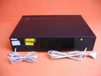
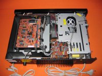
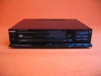
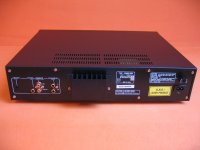
For sale - Philips CD304 & CD960 New Old Stock
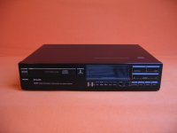
I just bought a CD304 and a CD960 for modifications but I am reluctant to work on them – they are NOS. NOS like in New Old Stock! The must have been bought by the first owner but never used. There are no scratches, dings or blind displays and the have the CDM1 drives with NEW lasers.
As I like to work on the old Philips CDPs, I would like to sell them to a collector. Modifying these would be a sacrilege. I am grateful to the followers of this thread who helped me quite a bit with the modifications of my CD204 and the CD204 MKII hybrid, therefore I am offering these players here first.
The CD304 comes with a (unused) remote, the CD960 without. For a reasonable offer, send me a mail to stefan.runge at gmx.de.
Best regards,
StefanAC
Attachments
100% agree with stefanac. Steal the signal at pin 1 after the first half of op-amp even if you liked to use tube buffer. Don't use a simple resisitor for I/U. I experimented with tubes there too. That does not spend is worth. Take the THS4032 and time and money saved.
Original there is a 3,3µF 50V nichicon not axial. I use there 3 x 1µF 40V tantal. Once i tryed there a 100µF i get problems.
Hi,
I am going to try out your advice. I have installed the THS4032 for I/V. It sounds nice actually!🙂
Do you suggest just simply to steal the signal from pin 1 for each channel and ground from around the opamps and take from there to tube buffer ?
Hi,
I am going to try out your advice. I have installed the THS4032 for I/V. It sounds nice actually!🙂
Do you suggest just simply to steal the signal from pin 1 for each channel and ground from around the opamps and take from there to tube buffer ?
On the Cd 104 / 304 pin 1 is right to get the signal after the I/U. But at some "newer" philipses the OP second half is used for I/U, there is pin 7 the right. Have a look at the manual from your CD 9000 ...
Can you mail me the manual?
- Home
- Source & Line
- Digital Source
- Philips CD104 tweaks