Hello tubee,
Not all voltages a regulated - between 45-1 and 45-2 you have got 2,3VAC for the display. On both of my CD204 I have measured 2,7VAC, while my CD304 MKII even has 5,4VAC (although the manual says it should also have only 2,3VAC). These voltages are directly proportional to the mains voltage.
But the main problem is with the regulators – their input voltage is over 8% higher while their output voltage remains the same. Therefore the regulator for -6V (6457) has to deal with a voltage drop of about 6V instead of 4,5V. And this is an increase by 1/3, resulting in higher thermal stress for the regulator and reducing its servicing life.
Best regards,
StefanAC
Hello Andreas,
I am writing my diploma thesis as a mechanical engineer right now and have some interest in electronics, but I am not an electrical engineer. Therefore I am not that well into the layout of circuits, but as far as I understand the thinking behind the de-emphasis circuit, its function is twofold. First it increases the signal by 6 dB/oct at 3180Hz (50us) and than it decreases the signal by 6 dB/oct at 10610Hz (15us). By removing R3562 and R3563, I think you have switched of the signal increase at 3180Hz and maintained the signal decrease at 10610Hz. So, switching on the de-emphasis circuit now creates a 6dB/oct low pass filter with a 10610Hz cut-off frequency. Without further knowledge, that might sound like putting a blanked over your speakers as the higher frequencies get muted. But all that is only an educated guess!
The switchable NOS modification is excellent work, I would be glad if I could do the same. I especially like the way you shortened the signal path when NOS is in use. In my 14bit CD204, I have mounted the cable jumpers and the 1k resistor on a second socket to switch between NOS and OS. And I was planning to do the same with my 16bit CD204 MKII, the hybrid. But that leads to a longer signal path than your solution incorporates and I need to open the player to do the switch. OK, due to the arrangement of the boards, switching can be done in under a minute in the CD204 (needs an open top cover) but not so in the CD204 MKII (needs an open bottom plate). And making an A/B comparison is far more difficult when some time has passed, so your impressions on the sound difference are very valuable.
Seeing those Bursons on the decoder board my first impression was – how will they fit into the chassis, they are HUGE. I think I will stick to op-amps than. And maybe get some Os-cons for the digital ICs as well, in case I ever find a cheap supplier! And Elna Slimic for the op-amps…
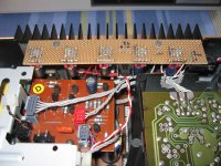
As the decoder board still seems to be work in progress, what are your plans for the decoupling caps of the TDA1541? I can see you already substituted two of the 220nF ceramics with film/foil caps on pin 13 (MSB) and pin 19 (one down on MSB). Common opinion is to use 1uF on MSB and the one down plus 0,47uF on the others. Wima MKS seem to work for some, others use orange Philips MKS. As the manual states these ceramics are NP0, I think I will stay with those and later add some other SMD caps to them.
I think the problem with my CD304 MKII with CD204 display, the CD204 MKII hybrid, seems to be homemade – I changed C2219 from 27nF to 100nF during my work on the servo board. I thought it was just some local decoupling cap that could be improved, but now I realize it is a low pass filter together with R3260 and I changed the cut-off frequency from 268Hz to 59Hz. Time to get the soldering iron hot again…
The CD204 with CD304 MKII display is working fine now; I just plugged and unplugged all cable connections. There seems to be a broken cable or loose connection somewhere, but I am not willing to search for it. It is just a parts donor!
Best regards,
StefanAC
I am writing my diploma thesis as a mechanical engineer right now and have some interest in electronics, but I am not an electrical engineer. Therefore I am not that well into the layout of circuits, but as far as I understand the thinking behind the de-emphasis circuit, its function is twofold. First it increases the signal by 6 dB/oct at 3180Hz (50us) and than it decreases the signal by 6 dB/oct at 10610Hz (15us). By removing R3562 and R3563, I think you have switched of the signal increase at 3180Hz and maintained the signal decrease at 10610Hz. So, switching on the de-emphasis circuit now creates a 6dB/oct low pass filter with a 10610Hz cut-off frequency. Without further knowledge, that might sound like putting a blanked over your speakers as the higher frequencies get muted. But all that is only an educated guess!
The switchable NOS modification is excellent work, I would be glad if I could do the same. I especially like the way you shortened the signal path when NOS is in use. In my 14bit CD204, I have mounted the cable jumpers and the 1k resistor on a second socket to switch between NOS and OS. And I was planning to do the same with my 16bit CD204 MKII, the hybrid. But that leads to a longer signal path than your solution incorporates and I need to open the player to do the switch. OK, due to the arrangement of the boards, switching can be done in under a minute in the CD204 (needs an open top cover) but not so in the CD204 MKII (needs an open bottom plate). And making an A/B comparison is far more difficult when some time has passed, so your impressions on the sound difference are very valuable.
Seeing those Bursons on the decoder board my first impression was – how will they fit into the chassis, they are HUGE. I think I will stick to op-amps than. And maybe get some Os-cons for the digital ICs as well, in case I ever find a cheap supplier! And Elna Slimic for the op-amps…
As the decoder board still seems to be work in progress, what are your plans for the decoupling caps of the TDA1541? I can see you already substituted two of the 220nF ceramics with film/foil caps on pin 13 (MSB) and pin 19 (one down on MSB). Common opinion is to use 1uF on MSB and the one down plus 0,47uF on the others. Wima MKS seem to work for some, others use orange Philips MKS. As the manual states these ceramics are NP0, I think I will stay with those and later add some other SMD caps to them.
I think the problem with my CD304 MKII with CD204 display, the CD204 MKII hybrid, seems to be homemade – I changed C2219 from 27nF to 100nF during my work on the servo board. I thought it was just some local decoupling cap that could be improved, but now I realize it is a low pass filter together with R3260 and I changed the cut-off frequency from 268Hz to 59Hz. Time to get the soldering iron hot again…
The CD204 with CD304 MKII display is working fine now; I just plugged and unplugged all cable connections. There seems to be a broken cable or loose connection somewhere, but I am not willing to search for it. It is just a parts donor!
Best regards,
StefanAC
Hello tubee,
Not all voltages a regulated - between 45-1 and 45-2 you have got 2,3VAC for the display. On both of my CD204 I have measured 2,7VAC, while my CD304 MKII even has 5,4VAC (although the manual says it should also have only 2,3VAC). These voltages are directly proportional to the mains voltage.
But the main problem is with the regulators – their input voltage is over 8% higher while their output voltage remains the same. Therefore the regulator for -6V (6457) has to deal with a voltage drop of about 6V instead of 4,5V. And this is an increase by 1/3, resulting in higher thermal stress for the regulator and reducing its servicing life.
Best regards,
StefanAC
That is a good reminder. Maybe that's the reason why the 5V dig supply LM317 reg gets awfully hot in my CD300. Cooled it better with a silicon pad with paste. I will check the 240 V option. The 304 gets some hot too btw.
The grey sockets are very sensitive for bad contacts. Best is to remove the wires, pull on the sockets after lifting the clip a little. Then fix the wiring order with cellotape on both ends, and mark pin 1 with a stripe or so. Then dismatle the socket (lightgrey/darkgrey) with lifting the small clips on both sides. Remove all small contacts, with a fine flat griptool press the fine fork a little smaller. This fork grabs into the solid core of the wire. Then refit all wires in good order, after cutting off about 3mm off the wire end. Press the socket together again with a small bench vice. Cut the wires coming slightly out of the socket and you have it new and original again.
Last edited:
Marvelously Stefan that you have found this mistake by looking at the picture!...you already substituted two of the 220nF ceramics with film/foil caps on pin 13 (MSB) and pin 19 (one down on MSB). Common opinion is to use 1uF on MSB and the one down plus 0,47uF on the others. Wima MKS seem to work for some, others use orange Philips MKS. As the manual states these ceramics are NP0, I think I will stay with those and later add some other SMD caps to them.

Thank You very much

The caps should go to the MIB so I solder them in place of the last smd in each row. I don't count them and did not notice that on the mk2 in one row the last is 1cm out of place 😕
The one down the MIB get the desoldered 220nF on top to double. The black at the MIB are 1µ Tantalums with the + to the ground as we expect -15V here.
An externally hosted image should be here but it was not working when we last tested it.
For what do you think is the red marked smd's under the filter. I can't found them in the manual and i have them only on 1 from 3 mk2 boards. On the top they were connect with 1µF to the +5 at 7210. The otherside goes to the 7220 clock sys to 7210. There are still few further deviations.
That was surely not what I wanted. A 6db cut at something over 10k 😱... First it increases the signal by 6 dB/oct at 3180Hz (50us) and than it decreases the signal by 6 dB/oct at 10610Hz (15us). By removing R3562 and R3563 ... creates a 6dB/oct low pass filter with a 10610Hz cut-off frequency.
I had a look at the manual and read that this circuit must be switching from 15µs to 50µs. I thougt the 15µ is given and the 50µs were switching by with the BSR56. That shows that I am not an expert in compute a filter. Rather in out-solder the filter 🙄
How do you think is it makeable to switch the De-em on and off with this given.
An externally hosted image should be here but it was not working when we last tested it.
The red is the position of the socket for the switch.
In the 304 there is 5mm space between them and baseplate. In the 104 there is 0mm! But it's not impossible to build in 104.Seeing those Bursons on the decoder board my first impression was – how will they fit into the chassis ...
An externally hosted image should be here but it was not working when we last tested it.
But final implemantation of burson is not finished. I have to rum-try some more and decide then between THS and Burson ...
Wow i am curious, a Burson/THS fight, wich one will be the winner. 
A friend of my want to add a simple IV in a CD880, i advised to chose the THS instead of a OPA627. The THS performs really well in my CD300. I am thinking of a nonos try out on it but not confident of the sound it will bring.
As you can see the THS4032 needs definately a small heatsink, still getting about 40 degr. C
The small chip does not like +/- 15V, in the CD300 it runs nicely on a +/- 12V
A friend of my want to add a simple IV in a CD880, i advised to chose the THS instead of a OPA627. The THS performs really well in my CD300. I am thinking of a nonos try out on it but not confident of the sound it will bring.
An externally hosted image should be here but it was not working when we last tested it.
As you can see the THS4032 needs definately a small heatsink, still getting about 40 degr. C
The small chip does not like +/- 15V, in the CD300 it runs nicely on a +/- 12V
Last edited:
After soldering back the R3562 and R3563 in de-em the first impression was that there a lot of "nos-sound" is gone. That is confirmed also while switching between OS and NOS the difference is much smaller. With switched de-em now from the blanket a towel became and the difference between OS and NOS is more less. That brings me back to my second idea.
With switched off de-em a 100% cut from the original de-emphasis for maximal NOS sound.
With switched on the original estate for less listen fartigue.
Now i agree 100% with that. The task is a compromise to find between maximally NOS sound and minimum listen fatigue. The possibility this filter switching by or not pleases me much.
Tubee, which filters you use with the tda1540?
ABOUT BURSON
Here is the circuit:
ABOUT THS
 And your pcb looks like you will polish them after each hearing 😀
Maybe it's better not to remove the resistors but connect the drains (D) from the two bsr65 in place 6514 and 6516 to the otherside of each resistor and cut the trace between resistors and the source (S) of the bsr n-fets.
An externally hosted image should be here but it was not working when we last tested it.
With switched off de-em a 100% cut from the original de-emphasis for maximal NOS sound.
With switched on the original estate for less listen fartigue.
... after a long listening time fatiguing occured. The i tried bessel analog filtering, and discovered it became less fatiguing, but also less non-os sounding...
Now i agree 100% with that. The task is a compromise to find between maximally NOS sound and minimum listen fatigue. The possibility this filter switching by or not pleases me much.
Tubee, which filters you use with the tda1540?
ABOUT BURSON
I canceled the Burson for the moment and mount sockets for testings. On the 14 bit 304 the Burson play musik but on the MK2 the Burson disorts in the highs also on a cd471. Has anyone an idea which cause can have that?
Here is the circuit:
An externally hosted image should be here but it was not working when we last tested it.
ABOUT THS
Agree! I build them in cd471 with +-15V. The THS likes more the eff. +- 10,5V in the 14 bit 304. He don't like sockets wich rush to something increase (dully 5532 don't care about sockets). I give him 1µ across pin 4 to 8. Your heatsink is the overkill tubee. Did you file from a piece?As you can see the THS4032 needs definately a small heatsink, still getting about 40 degr. C
The small chip does not like +/- 15V, in the CD300 it runs nicely on a +/- 12V
And your pcb looks like you will polish them after each hearing 😀
Last edited:
nanocamp; said:ABOUT THS
Agree! I build them in cd471 with +-15V. The THS likes more the eff. +- 10,5V in the 14 bit 304. He don't like sockets wich rush to something increase (dully 5532 don't care about sockets). I give him 1µ across pin 4 to 8. Your heatsink is the overkill tubee. Did you file from a piece?
😛Took an old TO220 PCB sink cut in half and half and chiseled it flat on all sides. The pcb is original 1983, only the small keramic caps changed to wima mks 0.1 uF If i can find my silvermica's again they might be added too.
Oh yes and the analog filter around the THS opamp is still original. (18dB butterworth @ about 44000 Hz if i am not mistaken)
That brings me to the question on the nonos quest: why occurs listening fatigue? What is the content of a nonos signal without filter, this must be only the 44kHz part. The ear can not hear this, but music with fast transients so mixed with a 44.1kHz sampling frequency is somehow detected by the hearing-section of the human brain.
That brings me to the question on the nonos quest: why occurs listening fatigue? What is the content of a nonos signal without filter, this must be only the 44kHz part. The ear can not hear this, but music with fast transients so mixed with a 44.1kHz sampling frequency is somehow detected by the hearing-section of the human brain.
Last edited:
Hello tubee,
Thank you for your advice on the rewiring procedure, but I already had to do that on my other CD204 when I added some additional LM317s and LM337s 🙂. I especially had problems when removing these delicate contacts from the old wire and the process of re-assembly would have been easier if I had used your tip with the cellotape.
Although I have not experienced a problem with listening fatigue with my NOS CD204 yet, could that be down to modulation of the frequencies in the audio band by frequencies that should be suppressed by the filter? During the D/A conversion, mirror spectrums are produced at 44,1kHz +/- 20kHz, 88,2kHz +/- 20kHz, 132,3kHz +/- 20kHz etc. Thus the first mirror spectrum is at 24,1kHz and rather close to the audio band. But than there is the analog filter of about 18dB and the most efficient filter of all – the human ear. Human hearing is down 80dB at around 20kHz (if you are very young, otherwise you can’t hear that frequency at all 🙂) and down more than 140dB at 24kHz. Which should be sufficient.
Or is it just the case that the NOS player become so revealing that problematic recordings are revealed and highlighted? On several recordings I thought my CD204 sounded somehow distorted, but by comparison with my T+A DVD 1210 R and close hearing, I realized that actually the record was distorted!
Best regards,
StefanAC
Hello Andreas,
One of my first interests in any TDA1541 application is what kind of decoupling cap is used. So it was pretty straight forward for me to find the mistake – actually my friend with the Grundig CD-9000 did somehow the same. He just did it with two caps, the MSB and the one down (and he is an electrical engineer 😀).
I had a look at my CD304 MKII yesterday and it is missing that ominous circuit on pin 9 (XSYS) of the SAA7220 as well. To be honest, I have no idea what that circuit is supposed to do. I had a look at the CD630 and CD960 schematics, too, and they don’t have it either.
As I have already mentioned, I am no expert on electronics. Therefore my advice for the de-emphasis is as follows – follow the circuit. For most CDs, we don’t need the de-emphasis circuit. That indicates that the BSR56 must be closed, indicating an appropriate voltage on the gate (BSR56 is a JFET). Said voltage is provided via R3543 (-4 is -12V) and ultimately R3561. To open BSR56, the voltage must be cancelled, a task that is fulfilled by BC858B. This bipolar transistor opens when the SAA7210 provides an appropriate current and passes the current from R3544 (+1 is +5V) on to R3561.
If you keep the switch in the indicated position, you can switch the de-emphasis circuit on when ever you want and have the greatest freedom of choice. But it can be misused, be it accidentally or deliberately, by the user (de-emphasis circuit active on a CD without pre-emphasis). In that case, a LED triggered by the SAA7210 is highly advisable to show the user if de-emphasis is needed or not. If you place the switch between the SAA7210 and the BC858B, the possibility of misuse is smaller – the user can not activate the de-emphasis circuit on a CD without pre-emphasis. The same is true if you place the switch between BC558B and R3543.
But that does not solve the real problem – the de-emphasis circuit ads to the critical feedback parasitic reactance. Therefore, it should be cut off from the feedback loop completely. It would be best to dispose of BC858B and BSR56 all together and put C2561, C2563, R3565 and an equivalent of R3563 on a separate board together with a switch. That would make the placement of the Bursons easier, too. Concerning the value of R3563, I have no idea how large that one should be. On the CD304 MKII (in parallel with BC858B) it is 4M7, while on the CD204 (in parallel with a Reed relays) it is 820K. So it might be good to measure the needed value with everything still in place and take the added resistance of the switch into account. Or you get rid of the de-emphasis circuit completely 😉!
Concerning the Bursons: Has the CD471 the same partial offset correction which the CD304 MKII has and the 14 bit player are missing? Or are there differences in the feedback loops between the 14 bit and the16 bit machines? I am not sure, but I think I read in a thread somewhere here on diyAudio that the Bursons are fine as a buffer but there seemed to be problems in I/U conversion.
While I was on my problem solving mission for my CD204 MKII, I measured how much space there would be for Bursons in an original CD204 – the resulting 30 mm appear to be a bit on the low side 🙂.
Best regards,
StefanAC
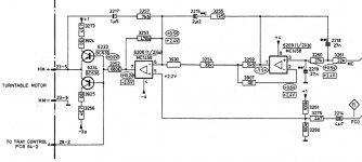
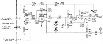
I still need help to get my CD204 MKII hybrid, a CD304 MKII with CD204 display, working. While I thought that the wrong value of C2219, which I changed from 27nF to 100nF by misjudgment, caused the problem, the exchange of the caps showed that that was not the case. The turntable motor still starts to spin directly after powering on the player and can not be stopped by any command.
Following that, I exchanged the servo board with the one from my other CD204. Both boards have the same MAB 8440P D041 installed and should function the same. The only difference is in the turntable motor control circuit – the CD304 MKII circuit looks like a cost cutting of the CD204 (or CD304) circuit. But the input and output currents seem to be the same.
When I switched on the CD204 MKII hybrid with the CD204 servo board, the problem of the constantly spinning turntable motor was solved. But I still could not make it play music. The hybrid reads an inserted CD and you can select a track, but on pressing start nothing happens. The CD instantly stops spinning. When you than select another track, the same happens. Any ideas would be appreciated!
Best Regards,
StefanAC
Attachments
That's what i try by removing the 3562 and 3563. But a switchable fs10k 6db must be changed naturally....the de-emphasis circuit ... it should be cut off from the feedback loop completely.
I measure at BSR between D and S switched 16,6Ω and unswitched ∞Ω. For the moment i leave only the 1k8 and 2n for I/U. The 3.order between first and second half of OP has gone also. Maybe i will try for that a switchable 6db low pass with 1k8 and 4n7 than after the BSR later....BSR56 must be closed, indicating an appropriate voltage on the gate
Offset correction was the first seen different between 304 and mk2 (471 don't have them) but it was not the cause. By solder them out did the distortions increase 😕 The only larger different remained was the 470µH in mk2 and 471 ... but not the cause. Building back till original estate brought no improvement at mk2Concerning the Bursons: Has the CD471 the same partial offset correction which the CD304 MKII has and the 14 bit player are missing? Or are there differences in the feedback loops between the 14 bit and the16 bit machines?
Than i test a 50Ω between DAC Out and ground and all distortions gone. It was a problem in I/U! But first the I/U and than a voltage follower was the reason to take an double Burson! I will try to variate the 1k8 in 3567I am not sure, but I think I read in a thread somewhere here on diyAudio that the Bursons are fine as a buffer but there seemed to be problems in I/U conversion.?
 But after mounting them on sockets for crossover testing i notized that one of them ever more distorts. The I/U resistors are absolut identically. They do not seem to be so outstanding selected thus nevertheles. After a closer i noticed that the assembly with transistor types on both is different. I don't know whether like that be a must 😕
Last edited:
I still need help to get my CD204 MKII hybrid, a CD304 MKII with CD204 display, working
A view days ago i had similar problems and search me a wolf on servo and display board. The error lay then somewhere on the decoder board around the 7210. Maybe on the 204 decoder is something different to the mk2 wich cause the problem. Have a look at 33-1 till 34-4 there.
Last edited:
...Or is it just the case that the NOS player become so revealing that problematic recordings are revealed and highlighted?
With see fatigues the eye also faster with a higher resolution.
Some preferentially even 5532 OP because he evenly not is so highly soluble.
Better you have a high resolution CDP with a switchable blanket 😀
Last edited:
Hello Andreas,
I think I will de-solder everything in the de-emphasis circuit and will use the resulting holes to get the signal right after the first half of the op-amp (as I recently did in my CD204). The analog filter in the second half of the op-amp will remain intact, as will be the signal grabbing point there. That way, I can easily switch between analog filtering or not – when the player is opened 🙂.
I have no personal knowledge of the Bursons, but I think the implementation of the I/U resistor is critical. Or are the modules defective?
The decoder board is one of the places I wasn’t expecting to be the origin of the turntable speed problem. I will have a look at the schematics soon, but I still wonder why the CD204 with CD304 MKII display is working fine while the much more important CD304 MKII with CD204 display is not. ARRGH!!!
Concerning listening fatigue, maybe the good old NOS TDA1540 give us an information overload that modern 24bit/192kHz Bitstream DACs are not capable of. Who knows 😉?
I am still wondering which components should be supplied with clean voltage in a CD304 MKII? My plans are for the op-amps (a +12V LM317 and a -12V LM337 for both), the SAA7220 (a +5V LM317) and the TDA1541 (a +5V LM317). Should there be a separate LM337 for the -6V for the TDA1541 as that voltage rail is shared with the servo board? And what are worthwhile components on the servo board?
Best regards,
StefanAC
After desolder the 1k8 I/U resistor and installing a pot in that place i noticed that the Burson has no more distortions when i adjusted more than 6k5 
I am still wondering which components should be supplied with clean voltage in a CD304 MKII? My plans are for the op-amps (a +12V LM317 and a -12V LM337 for both), the SAA7220 (a +5V LM317) and the TDA1541 (a +5V LM317). Should there be a separate LM337 for the -6V for the TDA1541 as that voltage rail is shared with the servo board? And what are worthwhile components on the servo board?
And i am still wondering if you will bring more than 6 regulators with adäquat caps in that. Around the necessary headsinks to save I installed them to the casting. With some large elna i get 5 regs on a standard pcb. +/-12 opamp, +/-5 DAC, and most important one +5 for the digitalfilter. Because of the big elnas there i had no mor place for a separat reg for the 7210. The -15 has it own reg in the psu. I take some good 78 and 79. The regs are excelent from TI.
At this time i searching for some chokes in the cardboard box beside my garbage pail to throw them after each new reg.
An externally hosted image should be here but it was not working when we last tested it.
I have no personal knowledge of the Bursons, but I think the implementation of the I/U resistor is critical. Or are the modules defective?
I mail them 18.Okt. I wait for answer.
Hi everybody!
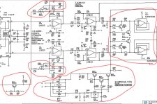
I did significant upgrades to my Grundig CD9000 and it sounds great. I'm planning in installing tube out via resistor I/V, but after reading this thread I decided in removing all of unnecessary parts off the board. I'm posting the part of schematic with parts that I want to remove marked in red (I already removed the muting tranies a while ago). Could someone please check so that I don't remove the parts that should stay 😉
I did significant upgrades to my Grundig CD9000 and it sounds great. I'm planning in installing tube out via resistor I/V, but after reading this thread I decided in removing all of unnecessary parts off the board.
I'm posting the part of schematic with parts that I want to remove marked in red (I already removed the muting tranies a while ago). Could someone please check so that I don't remove the parts that should stay 😉Attachments
Hello Andreas,
Space is no problem for me as I only take a small scale approach – I don’t rectify the raw AC and use dedicated smoothing caps 🙂.
I take the DC right after the main caps (C2452, C2458, C2469 and C2476), use a 100nF Wima MKS in front of the LM317/337 and a combination of 100nF Wima MKS and 100uF Panasonic FC afterwards. With careful placing of the two resistors and the safety diode, I only need 6 by 6 holes on a standard PCB for each regulator. There is still enough space for some chokes though, which I should try to get some time in the future.
I know it is not perfect that way, but I get a worthwhile improvement just by separating the supplies while I still maintain a neat layout.
Best regards,
StefanAC
Space is no problem for me as I only take a small scale approach – I don’t rectify the raw AC and use dedicated smoothing caps 🙂.
I take the DC right after the main caps (C2452, C2458, C2469 and C2476), use a 100nF Wima MKS in front of the LM317/337 and a combination of 100nF Wima MKS and 100uF Panasonic FC afterwards. With careful placing of the two resistors and the safety diode, I only need 6 by 6 holes on a standard PCB for each regulator. There is still enough space for some chokes though, which I should try to get some time in the future.
I know it is not perfect that way, but I get a worthwhile improvement just by separating the supplies while I still maintain a neat layout
.Best regards,
StefanAC
Attachments
- Home
- Source & Line
- Digital Source
- Philips CD104 tweaks