Thanks to help received from members of this forum, I'm glad to report that my CD104 has been revived.
While the machine was taken apart, I took the chance to change some capacitors, output op-amps, added more ground links on the servo board, added RCA sockets and fixed the ground loop issue at the heat sink pointed out in this forum.
The sound coming forth now is very musical and "analogue". There are plenty of details but the sound is never sharp. Mid and low frequencies have good tone and presence. Listening to vocals, wind or string instruments is a joy with the player.
Attached are some pictures of the modifications to the CD104.
An externally hosted image should be here but it was not working when we last tested it.
Hi all.
At my Cd 304 i removed the SAA7030 for NOS. Everything is ok when i take the signal at the original output. When i took the Signal direkt from pins 22 at the 1540P into a Tubestage i hear teribble noise with.
Q: What is the minimum to let beetween the dac pin22 and the tube.
The spec. of the Tubestage:
Different to the spec. i bridged the 1MicroF C1 at input
Attachments

Hi nanocamp,
I found during my internet research for my own CD204 project the two following websides that might be of interest for you:
http://www.lampizator.eu/LAMPIZATOR/REFERENCES/Philips CD104/CD 104 philips TDA.html
and
http://www.lampizator.eu/lampizator/REFERENCES/Philips Cd-304 MK-II/Philips cd304.html
I have no idea how a tubed output stage works, but maybe the value of the resistor for the I/V-conversion is to high and makes the pair of TDA1540s go into distortion. Or there is some DC left in the signal which is too much for your preamp.
By the way, have you added the 1k resistor between pin 16 and 18 on the SAA7000 to make it put out a 14bit signal?
Best regards,
Stefan
nanocamp said:Hi all.
At my Cd 304 i removed the SAA7030 for NOS. Everything is ok when i take the signal at the original output. When i took the Signal direkt from pins 22 at the 1540P into a Tubestage i hear teribble noise with.
Q: What is the minimum to let beetween the dac pin22 and the tube.
The spec. of the Tubestage:
Different to the spec. i bridged the 1MicroF C1 at input
TDA1540 is a current output DAC. As such it likes to see as low load impedance as possible ideally a zero. In order to amplify the signal coming out of the DAC you need to convert it to voltage(i/v converter). The most common i/v conversion is usually done by opamp, because the i/v opamp converter represents a virtual ground to the Iout of the DAC. Rising the load impedance of the DAC increases the distortion.
Now from the schematic attached we can see that the input impedance set by R* is 1Mohm which is A LOT more that the preferred 0ohm load for this DAC chip. This R* input resistor acts as a passive i/v conversion, turning the output current into voltage, which can be calculated using Ohm's law. Not only are you causing the DAC to output a tremendous amount of distortion, but the input tube is overloaded.
Speaking of the tube stage. How on earth did you chose this stage? You cant just stuck some tubes into the player and expect it to work.
If you really want a tube output stage you should try this out:
http://www.fortunecity.com/rivendell/xentar/1179/theory/vasfda/vasfda.html
As you can see the recommended I/V resistor for TDA1541 is 100ohm. This resistor is subject to experiments in order to find the correct value for your needs. In general the higher the resistor's value the higher the output level, but you get higher distortion as well.
Good luck 🙂
Quite impressive IC IMHO. And one can use those NULL pins to drive the DC output down to 0V. I've got some other favourites though, like SSM2017 😉 An excellent IC.
Hi Nanocamp,
I used the Lampizator tube stage in that link StefanAC provided. I would advise you to carefully read the word document Lukasz provides.
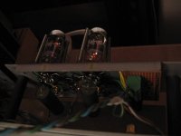
The SRPP tube stage is easy to construct and good to start with. As Simonov diagnoses you need to convert current out to voltage out. I simply used a 20 ohm resistor from pin 22 of the dac to ground. This is sufficient as the gain of the 6N2P in SRPP is about 50.
Used a small metal piece with the valves to ground the RCA (- ve) input, output, circuit (cathode R of bottom valve) and (- ve/ground) of the power supply. See pic attached (sorry about the quality)
I also used a different power supply with a valve rectifier and some chokes.
Rich
I used the Lampizator tube stage in that link StefanAC provided. I would advise you to carefully read the word document Lukasz provides.
The SRPP tube stage is easy to construct and good to start with. As Simonov diagnoses you need to convert current out to voltage out. I simply used a 20 ohm resistor from pin 22 of the dac to ground. This is sufficient as the gain of the 6N2P in SRPP is about 50.
Used a small metal piece with the valves to ground the RCA (- ve) input, output, circuit (cathode R of bottom valve) and (- ve/ground) of the power supply. See pic attached (sorry about the quality)
I also used a different power supply with a valve rectifier and some chokes.
Rich
Attachments

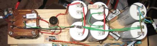
and here is a pic of the power supply. I'm using a separate filament transformer for the rectifier and 6N2p valves. Power supply is essentially 125V–0–125V – 6BW4 – 40uF – 330R – 40uF -15H 1K choke – 20uF. I’m getting 194V on the plate of the tubes.
Rich out
Rich out
Attachments
Thank you Stefan and simonof.
It was the I/V-conversion for my problem.
On the site for the universal tubeamp from Thorsten Loesch was 100 ohm recommended. Lampizator take a 80 ohm between DAC and tube. I try a lot of values, 80 ohm is the absolut highest - 100 ohm is much to high. As you told simonof, the lowest is the best for this DAC. So i had to find a good compromise between distortion and level for the tubeamp. In my case now i use a 50 ohm in paralel after change some values in the tubestage to get moderate level without distortion. Now it works fine!
This tube was laying around, so I want to give it a chance. It was designed by G.Haas for connection to a AKM DAC in Playstation. Simply to build and as a complete kit supplied.
Here the tubestage: (changed values are marked red)
tubestage
The tube with PSU is a little large to build in the cd 304, so it has to stay separat:
periphery
Since I read from the good quality of the old Philips with CDM1, I want to try one. Because of the comfort I decided for a brand new looking CD 304 with Remotecontrol and a broken CD 104 for Parts. My first impression with the stock:
The CD 304 has a warmly sound (blown up and not very precisely). That must it be what Consumers with bad Recording on CD helps to get audibly result. It was disappointing. My modified Playstation with extern linear PSU and this Tubestage was in each case better. So I want to modify the CD 304 too. At first I removed oversampling at it was told in this thread earlier. To remove oversampling shoud be the holy Gral for CD, but I was wondering that the Playstation was still better. So I want to remove the complete passive filters in the CD 304 to connect direkt at the DAC to compare it under same conditions with the same tube-outputstage. By this work I do some other mods was discribed in this thread. New lytics and in PSU bypassing them with small foils, decoupling and shielding the DACs. Not forget to resoldering all the griplets with wire. It’s easy to do. Without doing that and when getting defectly, to constitute very heavily as a cause - thanks to poynton for this.
back
front
A big Surprise after doing this – it was the best sound I ever heard. It has a fantastic frontstaging with very good broad and unbelievable deep progressive rate by very high precission. There was only a small unfairness in the comparison. The Playstation was not released from oversampling. Maybe later …
There was only two little problems left by removing all digital and passive filters on TDA1540 PCB.
First Problem:
I must renounce bad rekordings on CD, because that can only oversampling handle. For this maybe a switchable oversampling is the better solution.
Second Problem wich was described by JeroenR earlier:
Everytime when the DAC starts working there was a little “diggediggeliegg” from R2D2. Between the tracks this was quietly for some milliseconds audibly. Maybe a kind of softstart can solve this.
In this connection I have a question: At the pic of the stock PCB you can see a second Filter between the mutingtransistors and the op-amps (red marked at the pic below)
Q: Wich function this filter has?
For me the function is not clearly, and when this is used for a kind of softstart, than it’s a better solution to use this instead cutting of the hole outputstage. Maybe I change the op-amps with the THS4032 wich is recommended by tubee and is very goodlocking (the op-amp) and can direktly replacing the NE5532N. Just cut the rest of the Filters.
Andreas
It was the I/V-conversion for my problem.
On the site for the universal tubeamp from Thorsten Loesch was 100 ohm recommended. Lampizator take a 80 ohm between DAC and tube. I try a lot of values, 80 ohm is the absolut highest - 100 ohm is much to high. As you told simonof, the lowest is the best for this DAC. So i had to find a good compromise between distortion and level for the tubeamp. In my case now i use a 50 ohm in paralel after change some values in the tubestage to get moderate level without distortion. Now it works fine!
Originally posted by simonov
Speaking of the tube stage. How on earth did you chose this stage? You cant just stuck some tubes into the player and expect it to work.
This tube was laying around, so I want to give it a chance. It was designed by G.Haas for connection to a AKM DAC in Playstation. Simply to build and as a complete kit supplied.
Here the tubestage: (changed values are marked red)
tubestage
The tube with PSU is a little large to build in the cd 304, so it has to stay separat:
periphery
Since I read from the good quality of the old Philips with CDM1, I want to try one. Because of the comfort I decided for a brand new looking CD 304 with Remotecontrol and a broken CD 104 for Parts. My first impression with the stock:
The CD 304 has a warmly sound (blown up and not very precisely). That must it be what Consumers with bad Recording on CD helps to get audibly result. It was disappointing. My modified Playstation with extern linear PSU and this Tubestage was in each case better. So I want to modify the CD 304 too. At first I removed oversampling at it was told in this thread earlier. To remove oversampling shoud be the holy Gral for CD, but I was wondering that the Playstation was still better. So I want to remove the complete passive filters in the CD 304 to connect direkt at the DAC to compare it under same conditions with the same tube-outputstage. By this work I do some other mods was discribed in this thread. New lytics and in PSU bypassing them with small foils, decoupling and shielding the DACs. Not forget to resoldering all the griplets with wire. It’s easy to do. Without doing that and when getting defectly, to constitute very heavily as a cause - thanks to poynton for this.
back
front
A big Surprise after doing this – it was the best sound I ever heard. It has a fantastic frontstaging with very good broad and unbelievable deep progressive rate by very high precission. There was only a small unfairness in the comparison. The Playstation was not released from oversampling. Maybe later …
There was only two little problems left by removing all digital and passive filters on TDA1540 PCB.
First Problem:
I must renounce bad rekordings on CD, because that can only oversampling handle. For this maybe a switchable oversampling is the better solution.
Second Problem wich was described by JeroenR earlier:
Everytime when the DAC starts working there was a little “diggediggeliegg” from R2D2. Between the tracks this was quietly for some milliseconds audibly. Maybe a kind of softstart can solve this.
In this connection I have a question: At the pic of the stock PCB you can see a second Filter between the mutingtransistors and the op-amps (red marked at the pic below)
Q: Wich function this filter has?
For me the function is not clearly, and when this is used for a kind of softstart, than it’s a better solution to use this instead cutting of the hole outputstage. Maybe I change the op-amps with the THS4032 wich is recommended by tubee and is very goodlocking (the op-amp) and can direktly replacing the NE5532N. Just cut the rest of the Filters.
Andreas
Thanks at Richard too.
I wrote my last before you, but i'm new member and so it has read by moderator before it get visible.
I wrote my last before you, but i'm new member and so it has read by moderator before it get visible.
Mabe anyone knows about existing of pcb's of cd104 in pcad, .lay or other formats to build the modern pcb's. I find that 22 years past the technologies was not so good as we have today and thos psb's are pretty ugly, but to redraw whis "0" is a huge job, so I am asking about.
My Philips CD204 project is finally finished – the sound is excellent and I am running out of ideas for further mods. The CD-player is still early in its one week running in period, but it already is better in most areas than my (until now) unmodded T+A DVD 1210 R.
The DVD1210R has a Philips DVD-transport with VAL6011 laser, a DSP56362 with proprietary software for filtering and one AD1853 24/192 delta-sigma Iout stereo DAC per channel (as in the Accuphase DP-55V/DP-75V/DP/77/DP-85, the Benchmark DAC 1, the Lindemann CD1, the Mark Levinson No.390S, the Nagra DAC or the Spectral SDR-4000 to name but a few). For I/V-conversion and to go from a differential to single-ended signal, the T+A uses one AD823AN per channel, while a pair of OPA627AP see use as a buffer. The drive, the D/A-board and part of the power supply are shielded with copper plated metal cages. All in all, a CD/DVD-player with very good parts and premier engineering – quite a benchmark.
But while the T+A was more than 2000€ when new, I paid for the CD204 less than 90€ - including all the parts I needed for the upgrades. So I can only advise everyone with some basic DIY skills to get an old Philips CD, be it a CD304 if you need a metal faceplate and a remote, a CD104 if you like the slimline look, a CD204 if you prefer your player without SMD parts or even the CDx00/CDx03 series players if you prefer the really vintage look.
The mods I did to my CD204 were:
• Increasing the size of the decoupling caps around the two TDA1540 to 2x 1uF, 3x 330nF and 5x 100nF (Arcotronic MKT due to their size; barely audible),
• Installing some Neutrik RCA sockets and an IEC socket (my CD204 had build in RCA cables of lousy quality, therefore a must!),
• Resoldering ALL griplets on the servo and decoder boards (FIRST thing to do),
• Replacing all electrolytic capacitors on the supply board with Panasonic FC (with a higher voltage rating and increasing the capacity by 2-3 times; very good mod that improves sound AND functionality),
• Replacing all electrolytic capacitors on the servo board, decoder board, drive board and tray board with Panasonic FC 100uF/35V (again, improves sound AND functionality),
• Replacing C2515 with Wima MKS4 1uF/100V, C2228 with Wima MKS2 1uF/63V, C2214 with Wima MKS2 4,7uF/50V (someone said to me: if you can replace an electrolytic capacitor with a film/foil – do it! 😉),
• Replacing the output decoupling caps with Wima MKP10 2,2uF/400V and getting the signal directly after the op-amps via some CAT6 solid core copper wire (very good cap in this application without the high-end price; best in 400V rating or below due to construction; definitely one of the first mods that should be done – HUGE increase in sound quality),
• Damping the top plate, bottom plate and the drawer mechanism with bituminised felt (makes the complete player feel more solid as the flex of the bottom plate and the hollow sound of the top plate go away),
• Replacing the standard mounted feet with some better parts I had at hands (slightly higher ground clearance makes it easier to lift),
• Adding a dedicated voltage regulator for the drive (+/-12V, LM317/337), the DAC (+5V, LM317) and the op-amps (+/-12V, LM317/337)(next time I would use a 78xx/79xx series regulator as I placed everything on a board that I fastened upside down on the original power supply heat sink and therefore space was at a premium; apart from the time consuming nature of the mod a very good upgrade, especially with the improved op-amp decoupling),
• Replacing the op-amps with OPA2132PA in sockets (with a Wima MKS2 100nF/63V between pin 4 and pin 8; better than standard NE5532 but I will try a LM6172, LM4562 and THS4032 as soon as I get my hands on a pair of those),
• Replacing the op-amp decoupling caps C2617, C2618, C2619 with FOUR Panasonic FC 100uF/35V (Philips uses only small 22nF ceramic capacitors on the op-amps, C2617 is even shared for the +V supply! 😕),
• Adding mica insulations to ALL voltage regulators and getting rid of several ground loops (at the supply board and the decoder board, as was mentioned in this thread),
• Deleting the headphone amp board (it has no volume pot and was of no use to me),
• Cleaning the tray mechanism, sanding the wheels for the rubber belt and boiling the rubber belt for 4-6 min in hot water to get it into shape again as I had no replacement (works really well, the tray opens and closes each and every time now),
• Doing the NOS modification to the SAA7000 (lifting pin 16 from ground and connecting it to pin 18 with a 1k resistor; this makes the SAA7000 put out a 14bit signal) and SAA7030 (removing that chip and connecting pin 20 to pin 3, pin 17 to pin 10, pin 18 to pin 6 and pin 21 to pin 7 with some solid core wire) and
• Deleting the reed relays for muting and de-emphasis with ALL associated components on the decoder board (there already was a wire bridge on one channel of the muting relays when I bought the player; there are no noises when skipping tracks or on opening and closing the tray, e.g. in normal operation – but do not switch off the player when the amp is still on a high volume setting; the de-emphasis relay was not working correctly either – and I have not heard any problems with my CDs yet after I de-soldered everything; the improvement in sound quality after the mod was clearly audible; there seems to be less noise injection into the +5V rail and the signal path is way shorter).
I would like to stick to op-amps on the output or maybe build a small transistor output board, but due to limited skills I will not built a valve output stage. So it is interesting to read the findings of nanocamp, simonov, Richard et al about that. If you have any further suggestions, please let me know.
Best regards,
StefanAC
Hi Stefan,
Sounds like you have been busy.
You may want to consider some structural mods. I removed the top cover and the draw mechanism and turned it into a top loader. If you decide to do this you will need the puck from the original loading tray and a small magnet or add some mass to it. Be careful to investigate what the switching order is on the sliding mechanism so you can replicate it. There is a small push button switch behind the draw. The delay when you press the "open/close" button to when the draw presses this one should be about 2 seconds. Also remove that thin base and add a thick wooden one or just screw spikes (sharpened threaded rod) into the base of the player. Add some blutac to the heat sink (rub your nail on it before and after to see the difference)
In regard to the opamp output, by looking at the schematic you may be able to take the output from the 1st opamp see the lampizator website for this and his "snip it" mod. Also look at the datasheet schematic for single/dual opamps to replicate it.
Add small ferrite beads to the legs of chokes (look like green resistors) in the +5 rail.
And clock the SAA7000, start with a Kwak clock (with it's own transformer & power supply) and go from there.
Cheers,
Richard
Hello Richard,
You are absolutely right, some of these mods were quite time consuming for a novice like me. But they were worth it!
Your suggestions for further improving my CD204 are excellent and some of them are now on my list. But others will not be implemented do to appearance, cost and practicality.
The top loader conversion is a no go for me as I really like the look of my Philips – I removed the anthracite colour of my unit and sanded all the buttons on the front for a cleaner appearance. And retaining the standard enclosure makes handling the CD-player much easier.
Although I already applied damping sheets to the enclosure and base plate to good effect, changing the base plate to some birch ply wood seems like a good move.
BlueTac worked for me on the oscillator and some other components including the CDM1’s puck, but I had not thought of adding it to the heat sink. Good idea!
I was considering the use of only one half of the op-amp when I soldered in the sockets and implemented the dedicated power supply but stayed with both halves in use for the time being. This mod might be one of the next steps.
Ferrite beads on the chokes seem to be worth having as I have read in this post somewhere. I thought I could get away without them due to the separate power supplies and the other improvements I did to the different voltage rails.
Adding an after marked clock is out of question due to two main considerations. First, a new clock with power supply would cost as much as the whole player including the upgraded components cost me and therefore is not cost efficient. Second, with the NOS modification, a more precise clock is not necessary anymore (a good explanation for this can be fond under http://www.musicconnection.de/v7/index.php?link=100&id=14, only in German it seems). It is only important to isolate the clock power supply.
Best regards,
StefanAC
Any advice welcome
My beloved Grundig CD7550 has finally succumbed to failing to read the TOC until it warms up, normally after about 1/2 hour of being powered on. But sometimes I can leave it all day and it never rectifies itself.
I know this is a fairly common problem with the 104 based products but does anyone know the general causes of it. It’s not soldered joint issues on the servo board as I recently resoldered the entire board and sorted the griplet issue. I'm assuming its probably capacitor problems but any pointers would be appreciated.
Hi Ian01,
Try the following:
check power supply to decoder and display boards
check the crystal on the SAA7000
replace caps on the decoder board
check/resolder the connections from decoder to the display board
It may also be the capacitors on the CDM1, when I replaced these it gave the drive a whole new lease of life.
I had a similar problem with my 304, traced it to some loose connections on the clock that I replaced the crystal with.
Hope that helps
Richard
- Home
- Source & Line
- Digital Source
- Philips CD104 tweaks