Interesting, although you can easily reduce hum very significantly by decreasing the cathode impedance of the first stage as is done in my design. Notice how it is capacitively coupled to a much lower impedance feedback network.
Eli speaks the truth regarding the 6CA4, it's just not a good idea and puts more limitations on the design.
Eli speaks the truth regarding the 6CA4, it's just not a good idea and puts more limitations on the design.
Harlon, a cost effective chassis can be made out of a thick walled, deep, commercial kitchen, aluminum baking pan.Probly building with a new enclosure. Not sure by the time I strap on the new op trafos and choke that there will be much room to work. That and the enclosure is kind of bracketed together and not very sturdy.
Last edited:
Harlon, a cost effective chassis can be made out of a thick walled, deep, commercial kitchen, aluminum baking pan.
Yeah I've read a good bit as of late and came across that quote from you somewhere along the way. Not sure which way I'm going yet.
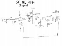
There is a correction to the signal schematic I uploaded. The non-nfb connection of the O/P trafo secondary gets grounded.
Eli, what is the function of the zvn0545a. What is it doing for the circuit. Is it boosting the signal from the 12ax7 to make up for its wimpyness?
Eli, what is the function of the zvn0545a. What is it doing for the circuit. Is it boosting the signal from the 12ax7 to make up for its wimpyness?
The FET is a DC coupled source follower, AKA buffer. It presents a very light, high impedance, load to the triode and it exhibits a low O/P impedance. Actually, all voltage followers exhibit a small voltage loss, but the current gain is substantial. As the increase in net load impedance (no O/P tube grid to ground resistance) the triode is exposed to raises gain, overall voltage gain for the 2 device composite is pretty much a "wash". OTOH, the impedance transform and current gain are GOLDEN.
 Also, the triode will be somewhat more linear.
Miller capacitance in full pentode mode EL84s is small and even the wimpy 'X7 triode is up to the task. Miller capacitance increases, when UL mode is employed, and the 'X7 triode rates to be "in over its head". The buffering FET ensures that all will be well.
There are all sorts of reasons for not using the 6CA4/EZ81, including the cost of a replacement. Save the tube for a future preamp project.
I'm uploading some "hen scratch" schematics that relate to my previous posts. The PSU assumes the power trafo already on hand will be recycled. I have not done all the "digging" needed to set some signal path parts values, sorry.
The PSU is slightly complicated and I'll explain why. It is fairly commonplace to bias signal tube heaters off B+, as a hum/noise control measure. Since the bias supply (C-) is derived from the 6.3 VAC filament winding, biasing off B+ is not available. Please notice that 1 side of the filament winding is grounded. Fortunately, the 1 A. of heater current reclaimed by eliminating the 6CA4 vacuum rectifier is quite sufficient to power both the bias supply and a 12 VDC heater supply for the 12AX7. Since we can't suppress hum 1 way, we'll suppress it another way.
BTW, Parts Express has a $16.88 special on soldering stations. The stock # is 374-100. Obviously, something this inexpensive lacks a temperature control probe in the tip. However, heat O/P level is adjustable. Somebody who only owns a simple iron would benefit by making the purchase.
Eli, don't know your background, but you'd make a great motivational manager or Dad for that matter. You simply refuse to accept my fear of SS, and my desire to avoid my fear of SS. If I lived closer I'd be begging to come over and have you walk me through it.
Guess I'm going with SS in the PS.
No they wouldn't. They're not designed to handle a DC component and would saturate.
Okay, thanks.
Couple more questions then I think I'm ready to start figuring out some parts orders.
1.) Incorporating the buffer for the 12AX7 and the CCS for opt cathodes and all the tweaks to the power supply will allow me to run UL with this tube configuration.
If I find that I don't like the UL sound will these additions disallow rewiring for pentode or triode operation?
2.) The intended source for this will be either an iPod or at times a older Sony portable CD player. I don't think a turntable Is part of WG's future. Will I need a separate preamp to boost the signal or would this amp be able to handle them as a direct plug in?
1. Yes you can rewire for pentode operation quite easily. If you are set on using a buffer then an IRF710 would be a better choice, much cheaper and more rugged.
2. Assuming you set the gain of the amp to a reasonable level and place a volume control pot across the input then it should be fine for CD and iPod. Using a turntable will require an RIAA preamplifier though.
Hope that helps.
2. Assuming you set the gain of the amp to a reasonable level and place a volume control pot across the input then it should be fine for CD and iPod. Using a turntable will require an RIAA preamplifier though.
Hope that helps.
The primary of a single-ended output transformer will make a fine choke, but... they're only designed for 40 mA of DC current and this design needs twice that. You could split the power supply and use one in each branch (each feeding one output tube), but will need filter caps for both branches. A typical 6BQ5 output transformer is about 5 Henries.
As for the source follower, I would say it's not absolutely necessary. The input (Miller) capacitance of the 6BQ5 is about 120 pF in triode mode and about half that in UL. Driven by the source impedance of the 12AX7 (about 50K), triode mode would have an upper -3dB point of around 30 KHz, UL would be about 60 KHz. Feedback will improve this further, at least at levels below full output. (Likewise, the lower end of the frequency response is improved by feedback, but only at lower power levels - the transformer has a power limit that decreases with frequency).
A 12AX7 has more gain than necessary for line-level inputs, so some can be used for feedback.
Schematic Contest Anyone
Everything has been very helpful and fun. Especially the back and forth over the details between you and Eli.
I was considering last night challenging you and Eli to a "schematic" off. I would build the amp based on the design of whoever posted a schematic fleshed out with values for all the circuit bits and pieces first.
1. Yes you can rewire for pentode operation quite easily. If you are set on using a buffer then an IRF710 would be a better choice, much cheaper and more rugged.
Hope that helps.
Everything has been very helpful and fun. Especially the back and forth over the details between you and Eli.
I was considering last night challenging you and Eli to a "schematic" off. I would build the amp based on the design of whoever posted a schematic fleshed out with values for all the circuit bits and pieces first.
1. Yes you can rewire for pentode operation quite easily. If you are set on using a buffer then an IRF710 would be a better choice, much cheaper and more rugged.
I disagree with the FET assessment. The ZVN0545A has proven to be a stellar performer, when driven by the 'X7 triode. Never, ever, forget that the 'X7 triode is a WIMP, with very little load driving capability. The ZV0545A is superior to the IRF710, in the crucial reverse transfer capacitance (Crss) parameter. Space considerations favor the E-Line case part vs. the TO220 case part. The price differential is small. A protective Zener diode will be needed, with either type, in this DC coupled application.
Rewiring an EL84 from UL mode to full pentode mode is easy enough. However, PSU changes are necessary. Best pentode open loop distortion is obtained by employing regulated g2 B+. If a regulator is not employed, an additional RC decoupling section has to be added between the plate supply reservoir cap. and the small signal RC decoupling section.
That's 2 votes for no buffer. It may be an idea for an amp where complexity isn't too much of an issue but this is a design where point to point wiring is needed.
If I fill out my topology with values you'll have to give me your word you'll build it . Photos or it didn't happen
I was considering last night challenging you and Eli to a "schematic" off. I would build the amp based on the design of whoever posted a schematic fleshed out with values for all the circuit bits and pieces first.
If I fill out my topology with values you'll have to give me your word you'll build it
. Photos or it didn't happen That's 2 votes for no buffer. It may be an idea for an amp where complexity isn't too much of an issue but this is a design where point to point wiring is needed.
I don't follow. Is Eli's ZVN suggestion not acting as a buffer? I've done some reading that supports the use of a MOSFET follower. Is this not a vote for a buffer? Or am I the first vote against(my skills), and Tom the 2nd?
If I fill out my topology with values you'll have to give me your word you'll build it
I'm game with one or two caveats.
1.) Power Supply: In the power supply I would like to use my old philco power trafo to start, if it fails I'll cry and deal with it then. I'd also prefer the open bracket triad choke. I think I'm going for the true embodiment of Whale Guano. So part values should reflect those specs.
The SAMS says it has 4 sections
1. 380 VAC @ .105 A
2. 6.3 VAC @ 2.8 A
3. 6.3 VAC @ 1.9 A
2.) Remember My Skill Level: I've recapped and wired this thing 3 times now, stripped out and wired it to work without the receiver parts, stripping it of parts to repair a 9304-20 that I recapped and had a bad choke I had to trouble shoot to figure out I blew a el84, etc,... Not incapable but not a pro by any means.
If I can follow it and you're willing to walk me through the parts I don't, I'd be honored to test your schematic and photograph it and even make a youtube video so you can hear it.
Please Answer One Real Bad Question
Eli,
One seriously terrible, but serious none the less question.
If I wanted to "honor" the true depths of Whale Guano's original design, could I tie in a center tapped push pull output trafo in the b+ prior to the se trafos as in the original schematic and drive a third speaker without destroying the rest of the UL SE part of the circuit? Would it leach off too much B+ and throw everything off voltage wise or would the UL taps on the SE trafos prevent any or enough signal getting to the PP trafo to produce any audio output?
Please answer? Dumb as it probably is this is a real question. If it would work I'd love to run the b+ through a switch that would allow either to run through a PP(whale guano style) or be bypassed and run full UL SE.
Stick to two SE output transformers, the Philco design is bloody awful.
Opinion aside, I know it's awful but is it doable to insert into your UL SE EL84 circuit? If you take me up on the schematic build offer I PROMISE I won't build it. But would it work?
Depends what you mean by 'work'. It's designed to drive two mid range speakers and a woofer, as opposed to 2 conventional hifi speakers. You'd be adding another impedance in series with the UL output transformers which would severely limit the amount of power you could get out of it.
- Status
- This old topic is closed. If you want to reopen this topic, contact a moderator using the "Report Post" button.
- Home
- Amplifiers
- Tubes / Valves
- Philco K1629 Upgrade Options