OP Transformer Wattage selection
Seems to be 3 numbers associated with output iron. Inbound impedance, outbound impedance and wattage.
I believe the inbound is a function of the output tube, and the outbound is a function of the speaker type.
What is the wattage a function of? Or more importantly what do more watts get you. And is there a ceiling.
For example. If a gx15-8-5k is good is a cx25-8-5k that much better?
Harlon
You size the O/P transformers' wattage rating according to the power yield of the O/P tube(s).
You have SE 6BQ5s, which yield about 5 W. In order to support the global NFB loop needed to get nominally 40 Hz. "iron" down another octave, plenty of magnetic headroom is needed. Use Edcor's GXSE15-8-5K O/P transformers.
You have SE 6BQ5s, which yield about 5 W. In order to support the global NFB loop needed to get nominally 40 Hz. "iron" down another octave, plenty of magnetic headroom is needed. Use Edcor's GXSE15-8-5K O/P transformers.
Thanks, so overkill is only good to a point.
I'm pretty set on sticking with the 6BQ5 O/P tubes for the rehash of WG. Moving backwards through the amp, Eli mentioned earlier that the 12AX7 may not be up to the task of driving the O/P tubes in UL mode. Do you have any recommendations on any other common preamp tubes that might do a better job.
Eli recommended boosting the tube with a FET, but since I'm starting from scratch, I'm not opposed to replacing the 12AX7 if there is a good 2nd option.
I'm pretty set on sticking with the 6BQ5 O/P tubes for the rehash of WG. Moving backwards through the amp, Eli mentioned earlier that the 12AX7 may not be up to the task of driving the O/P tubes in UL mode. Do you have any recommendations on any other common preamp tubes that might do a better job.
The screen grid in a 6BQ5/EL84 is plenty tough. So, UL mode "finals" make considerable sense, given the "short" B+ rail. Unfortunately, the 12AX7 triode is a wimp, which may not be up to driving a UL mode O/P tube.
Eli recommended boosting the tube with a FET, but since I'm starting from scratch, I'm not opposed to replacing the 12AX7 if there is a good 2nd option.
Go with the FET buffer.  It's inexpensive and it will increase the gain/linearity of the 12AX7 voltage amplifiers. The 12AT7 you mentioned earlier is not (IMO/IME) a good choice in SE setups, due to its distortion spectrum. The 6GK5 might be OK for the voltage amplifier, but you need 1 tube/channel.
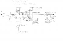
Take a look at the FET in the preamp schematic I've uploaded. Use an analogous protective 12 V. Zener diode from gate to souce of the ZVN0545A. Always wear an anti-static wrist strap, when handling MOS semiconductors. MOS semiconductors are extremely vulnerable to static discharge, which destroys them.
The low O/P impedance of a FET buffer allows use of 100 Kohm 6BQ5 grid to ground resistors. Your O/P tubes will NOT run away, regardless of the biasing scheme chosen.
Definitely use SS rectified B+. The 6CA4 heater current saved will be voltage multiplied to obtain a negative bias (C-) rail. You are going to end up with a quite nice 5 WPC stereoblock.
It's inexpensive and it will increase the gain/linearity of the 12AX7 voltage amplifiers. The 12AT7 you mentioned earlier is not (IMO/IME) a good choice in SE setups, due to its distortion spectrum. The 6GK5 might be OK for the voltage amplifier, but you need 1 tube/channel.Take a look at the FET in the preamp schematic I've uploaded. Use an analogous protective 12 V. Zener diode from gate to souce of the ZVN0545A. Always wear an anti-static wrist strap, when handling MOS semiconductors. MOS semiconductors are extremely vulnerable to static discharge, which destroys them.
The low O/P impedance of a FET buffer allows use of 100 Kohm 6BQ5 grid to ground resistors. Your O/P tubes will NOT run away, regardless of the biasing scheme chosen.
Definitely use SS rectified B+. The 6CA4 heater current saved will be voltage multiplied to obtain a negative bias (C-) rail. You are going to end up with a quite nice 5 WPC stereoblock.
Attachments
Wait, you need a negative supply as well?
Why not use the other triode in the ECC83 as a low impedance buffer to drive the grid and keep the circuit simple and away from JFETs. An IRF710 will also make a good high voltage buffer.
Remember, the more stages there are, the less stable the amplifier will be. Keep it simple I say. An ECC83 drives an EL84 quite nicely regardless as to whether it is in pentode, triode or UL operation.
Remember this guy is trying to build himself a simple amplifier .
Why not use the other triode in the ECC83 as a low impedance buffer to drive the grid and keep the circuit simple and away from JFETs. An IRF710 will also make a good high voltage buffer.
Remember, the more stages there are, the less stable the amplifier will be. Keep it simple I say. An ECC83 drives an EL84 quite nicely regardless as to whether it is in pentode, triode or UL operation.
Remember this guy is trying to build himself a simple amplifier
.I don't trust the 'X7 triode, whenever the load is other than HIGH impedance. The type is a wimp. The capacitances of the ZVN0545A are small and even the wimpy 'X7 triode easily drives them.
The FET buffer is DC coupled and does not increase the coupling cap. count. Therefore, stability is not adversely impacted. I too worry about phase shift oscillation setting in.
The FET buffer is DC coupled and does not increase the coupling cap. count. Therefore, stability is not adversely impacted. I too worry about phase shift oscillation setting in.
I was talking more about HF instability TBH. But really the OPTs frequency response is limited so much that you really have to get it wrong for anything to happen.
EL84 is fairly high impedance. I assume the valve we are talking about is the Yank equivalent. Should be fairly safe .
EL84 is fairly high impedance. I assume the valve we are talking about is the Yank equivalent. Should be fairly safe
.Yes, 6BQ5 and EL84 are 2 designations for a power pentode of a specific character.
I suggest "fixed" bias O/P tubes, given the fact that the B+ rail voltage will be on the low side. The grid to ground resistance limit is lower, when "fixed" bias is employed. Between that fact and the fact that UL mode tubes are more difficult to drive than full pentode mode makes me think of buffering the wimpy 'X7 voltage amplifier.
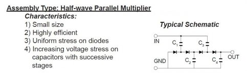
A 3 stage 1/2 wave parallel multiplier energized by the 6.3 VAC filament winding should be quite sufficient for the Class "A" setup that must be employed. The sample multiplier I've uploaded is for a 4 stage positive rail. Turn the diodes around for the negative rail this project requires.
I suggest "fixed" bias O/P tubes, given the fact that the B+ rail voltage will be on the low side. The grid to ground resistance limit is lower, when "fixed" bias is employed. Between that fact and the fact that UL mode tubes are more difficult to drive than full pentode mode makes me think of buffering the wimpy 'X7 voltage amplifier.
A 3 stage 1/2 wave parallel multiplier energized by the 6.3 VAC filament winding should be quite sufficient for the Class "A" setup that must be employed. The sample multiplier I've uploaded is for a 4 stage positive rail. Turn the diodes around for the negative rail this project requires.
Attachments
Skill Set Concerns
How concerned should I be about my skill set in regards to adding SS CCS and rectifiers etc into my design.
I'm thinking I may need to stick to tubes, capacitors and resisters in the design to compensate.
I've only worked on point to point wiring with traditional components. Most SS, if not all, examples I've found online have been breadboarded. Also, I understand they're much easier to burn up with over zealous soldering.
Can the CCSs and SS Rectifiers we've discussed using be point wired?
Perhaps a buffer is a good idea. A 12AX7 buffer might not be suitable as it requires a voltage at the cathode of less than 90V if the heaters are not elevated. Which will hurt the performance of the preceding stage if you are not using capacitive coupling (which has it's own problems).
A good simple solid state buffer would be a MOSFET, I think IRF710 is best.
A good simple solid state buffer would be a MOSFET, I think IRF710 is best.
Monty, the schematic you posted earlier for your improved el84 SE UL design. Have you got a working amp built yet based on the design? The reason I asked is that, if so are you happy with the sound and performance of the design. Fear of my soldering skills aside, I would like to avoid building something that is untried. Seems that a lot of the discussion going on between you, Eli and I is as it comes problem solving. Financially and maritally I've got one shot at doing this right. If you're still in the "working out the details" stage maybe I should look for a more tried design.
If we're good, I'm looking to build your amp design with my tube rectifier and a clc for power.
Hope this hasn't offended.
Wife already thinks I've spent too much time recapping and tweaking her 9304-20 stereo, doesn't know why I need another amp. If she only knew my future plans. ��
If we're good, I'm looking to build your amp design with my tube rectifier and a clc for power.
Hope this hasn't offended.
Wife already thinks I've spent too much time recapping and tweaking her 9304-20 stereo, doesn't know why I need another amp. If she only knew my future plans. ��
Harlon,
For UL you will need some good quality supply filtering. CLC is a good idea. Ideally your inductor will need a value of over 5H and capacitor values should be over 100uF as long as you use a solid state rectifier.
If you like a can draw you up a UL SE circuit which is a little simpler and does not use so many CCS.
I haven't built the circuit yet, although I will at some point before the new year.
The Maggie 8601 circuit is more than good enough - it's about as simple as it gets (once the unwanted EQ components are removed) - there's a lengthy thread on it on another audio board. (WARNING 300 posts! Magnavox Flea Power: Getting More Out Of The 8600 Series - A Lot More! - AudioKarma.org Home Audio Stereo Discussion Forums) Yes, SE needs good filtering though pentode mode is most forgiving - a choke would be essential with UL or triode wiring.
How concerned should I be about my skill set in regards to adding SS CCS and rectifiers etc into my design.
I'm thinking I may need to stick to tubes, capacitors and resisters in the design to compensate.
I've only worked on point to point wiring with traditional components. Most SS, if not all, examples I've found online have been breadboarded. Also, I understand they're much easier to burn up with over zealous soldering.
Can the CCSs and SS Rectifiers we've discussed using be point wired?
You certainly can wire diodes and other leaded SS parts P2P. Either surgical hemostats or spring loaded clips specifically intended for the job are clamped on the lead to be soldered close to the part's body, before applying heat to the joint.
Another technique for the employment of "sand" parts is perf. board mounting, along with the associated passive components.
This threads going to go on for ages unless we come up with a schematic.
Harlon, give me an audiocall on Skype at some point if you want some help. I think you want to go with a very simple design. CLC filter to the top of the UL transformer, then RC to the 12AX7 stage. Just use resistor cathode biasing and then you'll end up with something easy and simple to build, and more importantly troubleshoot if you make any mistakes.
Harlon, give me an audiocall on Skype at some point if you want some help. I think you want to go with a very simple design. CLC filter to the top of the UL transformer, then RC to the 12AX7 stage. Just use resistor cathode biasing and then you'll end up with something easy and simple to build, and more importantly troubleshoot if you make any mistakes.
It's been recommended multiple times to use a SS rectifier to get the b+ hot enough for running UL.
Would running 2 6ca4s in series one after the other work to get things hot enough. Using the xpwr146 suggested would this bump me from 200 to 230 and then 260 with the second tube?
Monty, on your schematic what is the purpose of the group of resisters, caps and KSP94s in the upper left. Are these working as like the rc part of a power supply to get the voltage down for the 12ax7/ECC83 plate? Why all the extra layers? Does this smooth things out to get a steadier voltage for the tubes because of the UL?
I've struggled to find a schematic or thread where someone has built a two channel SE UL amp with the single 12ax7 to dual 6bq5 configuration I have. Or really with any dual triode preamp type tube.
Is this because of the "wimpy" nature of the 12ax7 and like tubes. Just wondering why it hasn't been done? Or is it just that I'm not finding it?
I think the RH84 and 8601 both use the cousins of the 12ax7, the 12at7 and 6eu7 respectively. Has anyone experimented with going UL with either of these amp designs?
I'd stick with the old power transformer if it hasn't got any problems.
190V-0-190V will give you a B+ of about 250V once rectified with a suitable pair of diodes, which is about right for a 5K transformer.
Just for my learning purposes would running 2 6ca4s in series work?
- Status
- This old topic is closed. If you want to reopen this topic, contact a moderator using the "Report Post" button.
- Home
- Amplifiers
- Tubes / Valves
- Philco K1629 Upgrade Options