Hi all,
In Class-D amplifier, the transistors are in Push-Pull configuration. To drive the transistors using the PWM signal, the signal given at either transistor is inverted of the other signal.
The question is:
From most of the references I read, why they normally used 180 degree phase shift?? If PWM phase is shifted, it is not exactly inverted. Both signals which drive the transistors are not inverted to each other, but only delay.
Could somebody explain this to me. TQ.
Last edited:
However some waveforms are asymmetric; for example, a sawtooth wave is asymmetric. There is no phase shifted sawtooth wave that is equal to an upside-down sawtooth wave.If phase is shifted 180°, it is exactly inverted.
The output of a trumpet is another asymmetric waveform; see Fig 3.1 of this set of lecture notes. Phase shifting a trumpet wave doesn't give an upside-down trumpet wave.
Then, why some of the design of Class-D power amplifier use rat-race circuit or any other phase shifter hybrid to invert the PWM input signal, which is clearly not asymmetric?
However some waveforms are asymmetric; for example, a sawtooth wave is asymmetric. There is no phase shifted sawtooth wave that is equal to an upside-down sawtooth wave.
The output of a trumpet is another asymmetric waveform; see Fig 3.1 of this set of lecture notes. Phase shifting a trumpet wave doesn't give an upside-down trumpet wave.
I may not understand you correctly, but if I do, I can't agree
An inverted sawtooth, e.g. by using an opamp in the inverting configuration, is exactly that. And the same goes for the output of a trumpet. It's the same signal, upside down.
Stop thinking of it as a 180º phase shift. It is NOT a 180º phase shift, because it is NOT frequency-dependent, AND ESPECIALLY, it is not time-lagging!!! (which is what a -180º phase shift would have to have, and be a shift in the Z-plane domain)
Textbooks and popular literature very often call the waveform inversion "180º phase shift", but in so doing, they perpetuate the false reality.
We used to say that a "complimentary waveform" is made/created/used/employed. A waveform that is the "mirror image" of the positive waveform, with all wiggles that go up, reflected to go down, and vice-versa.
So, if you think about it like that, an "inverted sawtooth" or even harder to visualize, an "inverted triangle waveform" ... easily has a mirror of itself in the time-domain.
Indeed, ideally, W(t)inverted = -W(t), showing simple sign inversion. In the case of some amplifiers, the "phase splitter" (again, terribly misnamed, which should be called "symmetric signal inverter") not only creates the mirror-image, but also adds a bias to each (which might not be even the same!]. That's what stage-to-stage coupling capacitors are for: to remove the persistent DC/bias component, leaving Inverted = -Uninvderted;
GoatGuy
1.
Inverted non-sinusodioal periodic waveform generated by an (ideal) opamp inverter: ALL frequencies (fundamental as well as harmonics are 180° out of phase). wave looks mirrored upside down.
2.
time shifted non-sinusodial periodic waveform (shifted by a half period): ONLY the fundamental is 180° out of phase, the harmonics have different phase shifts.
Then, how could I drive transistors in push-pull configuration with PWM signal? The duty cycle of the pulse in the PWM signal keeps on changing.
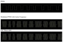
Do I need to modulate the signal first with sinusoidal carrier frequency, and only then the phase shift will work like an inverter. Is it the right method to drive class D amplifier or not? I can use the modulated signal and its inversion as shown below to drive both transistors in push-pull?
Do I need to modulate the signal first with sinusoidal carrier frequency, and only then the phase shift will work like an inverter. Is it the right method to drive class D amplifier or not? I can use the modulated signal and its inversion as shown below to drive both transistors in push-pull?
Attachments
In a half bridge, both transistors must never be ON at the same time, but it is desirable to have dead time as low as possible. So, the goal is to have almost always exactly one of the 2 FETs ON. This can be accomplished by generating a PWM signal for upper FET, then logically inverting this signal and feeding it to lower FET.
"1.
Inverted non-sinusodioal periodic waveform generated by an (ideal) opamp inverter: ALL frequencies (fundamental as well as harmonics are 180° out of phase). wave looks mirrored upside down.
2.
time shifted non-sinusodial periodic waveform (shifted by a half period): ONLY the fundamental is 180° out of phase, the harmonics have different phase shifts."
-> Since no one corrected my posting above, I ll do it myself: The truth is:
1.
Inverted non-sinusodioal periodic waveform generated by an (ideal) opamp inverter: ALL frequencies (fundamental as well as harmonics) are 180° out of phase in relation to the non-inverted signal. Wave looks mirrored upside down. OK.
2.
time shifted non-sinusodial periodic waveform (shifted by a half period): ONLY the fundamental AS WELL AS THE UNEVEN / ODD HARMONICS are 180° out of phase in relation to the non-shifted signal, the EVEN harmonics will see zero (360° or 360° * 2 or 360° * 3...) phase shift .
- Status
- Not open for further replies.
- Home
- Amplifiers
- Class D
- Phase Shift or Polarity Inversion??