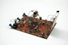
The Vref regulator isn't all that messy. Its reasonably compact and uses carefully laid out hand wiring.
Not like some of the early dead-bug stuff I did with ES9038Q2M. That said, dead-bug over ground plane is a useful technique for some prototyping.
Not like some of the early dead-bug stuff I did with ES9038Q2M. That said, dead-bug over ground plane is a useful technique for some prototyping.
Just to give you some perspective the Vref regulators on all my DAC boards (4-layers) are about 10mm from the DAC with as wide and short tracks as possible. So your tales of Vref regulator on a separate board hanging from 3cm long wires combined with ESS advise goes to waste.
I was asked a question regarding regulator distance from the dac, given an AK4499 eval board is involved. If you don't like not being able to get much closer why don't you complain to AKM not me?
I don't mean DC current. I mean does current vary with signal? How does it vary? Is it 22mA average with an AC component proportional to signal? Or a harmonic of signal, like ESS when not used with a differential IV? What are the HF components?In my case it draws 22mA per channel.
Last edited:
Haven't measured it. Most likely is rather similar to ESS. Its a switched resistor dac that needs opamp IV.
Here's what AK4499 datasheet has to say about it:
"Connect a 0.1μF ceramic capacitor and 2200 μF electrolytic capacitor between the VREFHL1/R1/L2/R2
pin and the VREFL L1/R1/L2/R2 pin.
The VREFHL1/R1/L2/R2 and VREFL L1/R1/L2/R2 pins should avoid noises from other power supplies.
Connect the VREFHL1/R1/L2/R2 to the analog 5.0V via a 1Ω resistor, and the VREFL pin to the analog
ground via a 1Ω resistor when it is difficult to obtain expected analog characteristics because of noises
from other power supplies (A low pass filter of fc=36Hz will be composed with the 2200 μF capacitor
and the 1Ω resistor. It removes signal frequency noise from other power supply lines). However, the
direct voltage at the VREFHL1/R1/L2/R2 and VREFL L1/R1/L2/R2 pins drops ±23 mV since a current of
±23 mA flows at VREFH/L via 1 Ω resistor.
The ceramic capacitors should be connected as near as possible to the pins. All digital signals,
especially clocks, should be kept away from the VREFHL1/R1/L2/R2 and VREFLL1/R1/L2/R2 pins in
order to avoid unwanted coupling into the AK4499."
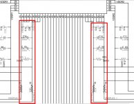
EDIT: Attached below is part of eval board schematic showing the Vref bypass caps located on the DAC chip daughterboard. Those caps remain intact. The discrete Vref supply attaches where R13 and or R22_1 would go if they were populated. The 10-ohm resistors are bypassed for ground, and open for Vref.
I don't have any particular reason to believe there is a problem with this arrangement, although it has not received close investigation by me.
Here's what AK4499 datasheet has to say about it:
"Connect a 0.1μF ceramic capacitor and 2200 μF electrolytic capacitor between the VREFHL1/R1/L2/R2
pin and the VREFL L1/R1/L2/R2 pin.
The VREFHL1/R1/L2/R2 and VREFL L1/R1/L2/R2 pins should avoid noises from other power supplies.
Connect the VREFHL1/R1/L2/R2 to the analog 5.0V via a 1Ω resistor, and the VREFL pin to the analog
ground via a 1Ω resistor when it is difficult to obtain expected analog characteristics because of noises
from other power supplies (A low pass filter of fc=36Hz will be composed with the 2200 μF capacitor
and the 1Ω resistor. It removes signal frequency noise from other power supply lines). However, the
direct voltage at the VREFHL1/R1/L2/R2 and VREFL L1/R1/L2/R2 pins drops ±23 mV since a current of
±23 mA flows at VREFH/L via 1 Ω resistor.
The ceramic capacitors should be connected as near as possible to the pins. All digital signals,
especially clocks, should be kept away from the VREFHL1/R1/L2/R2 and VREFLL1/R1/L2/R2 pins in
order to avoid unwanted coupling into the AK4499."
EDIT: Attached below is part of eval board schematic showing the Vref bypass caps located on the DAC chip daughterboard. Those caps remain intact. The discrete Vref supply attaches where R13 and or R22_1 would go if they were populated. The 10-ohm resistors are bypassed for ground, and open for Vref.
I don't have any particular reason to believe there is a problem with this arrangement, although it has not received close investigation by me.
Attachments
Last edited:
And some work by Jim Williams. You do know who he was, don't you guys?My thoughts exactly.
Please, stop embarrassing yourselves.
https://computerhistory.org/blog/an-analog-life-remembering-jim-williams/
Attachments
Before you embarrass yourself more what do your posts have to do with the thread topic?Please, stop embarrassing yourselves.
The shortcut is just to not ask Mark if he’s measured anything, because the answer is no 99% of the time 🙂. When the world feels like it’s going crazy, it’s comforting to see that some things never change.I don't mean DC current. I mean does current vary with signal? How does it vary? Is it 22mA average with an AC component proportional to signal? Or a harmonic of signal, like ESS when not used with a differential IV? What are the HF components?

I wonder how package and voltage rating influence this also. I know you’ve already tested a few permutations, but I do wonder if a larger package performs better, or even automotive “soft” termination with epoxy caps.I made still some further tests. First I changed the Cset capacitor to 10uF/50V X7R. This has over 80% capacitance left at 5V.
Here is the same measurement as earlier. Not much improvement to X5R.
View attachment 1069579
Then I wrapped the dac board with speaker polywool and placed it within a steel kettle.
View attachment 1069580
Clear improvement. About as good as tantalum polymer.
So piezoelectric microphony is a very probable cause. And it seems that Class II capacitors can be used in LT3042 Cset provided that proper shock mounting or noise damping is implemented.
Anyhow IMO all this just proves that Vref implementation is very critical for DS dacs. Even small imperfections can easily overshadow the potential benefits from low close-in phase noise clocks.
The only way to know how well it works is to take some measurements. Without measurements your promotion of this solution is akin to snake-oil business.I don't have any particular reason to believe there is a problem with this arrangement, although it has not received close investigation by me.
Cset Cap on my board is 1206. I have not tried soft/flex terminated class II caps. But regarding package size my thoughts were actually opposite: could it be that larger package is more prone to piezoelectric microphony.I wonder how package and voltage rating influence this also. I know you’ve already tested a few permutations, but I do wonder if a larger package performs better, or even automotive “soft” termination with epoxy caps.
The chip designers went the extra mile and added a gorillion VREF pins for each channel, presumably to reduce crosstalk and impedance...The VREFHL1/R1/L2/R2 and VREFL L1/R1/L2/R2 pins should avoid noises from other power supplies.
Connect the VREFHL1/R1/L2/R2 to the analog 5.0V via a 1Ω resistor, and the VREFL pin to the analog
ground via a 1Ω resistor when it is difficult to obtain expected analog characteristics because of noises
from other power supplies
And the board ruins that by ensuring high impedance and inductance to ground.
Sad.
Regarding all the fixation on measurements, I'm still waiting for someone to show that perceived SQ can reliably be predicted from measurements.
Otherwise its just looking for car keys under the streetlight because the light is better there: https://www.diyaudio.com/community/...quality-between-some-dacs.386815/post-7041012
Otherwise its just looking for car keys under the streetlight because the light is better there: https://www.diyaudio.com/community/...quality-between-some-dacs.386815/post-7041012
I'm still waiting for someone to show that perceived SQ can reliably be predicted from your subjective sighted listening tests.
It's fine to have that goal, but I don't think it should be discussed in every thread concerning specific topics, in this case phase noise in DS dacs.Regarding all the fixation on measurements, I'm still waiting for someone to show that perceived SQ can reliably be predicted from measurements.
Otherwise its just looking for car keys under the streetlight because the light is better there: https://www.diyaudio.com/community/...quality-between-some-dacs.386815/post-7041012
One of the problems is that SQ is subjective. Some may prefer the sound of a tube amp with lots of distortion and that's fine with me. But it would be useless for e.g., an audio analyzer.
In this case I am more interested in discussing/learning about reference noise and clock noise. And I think that bohrok2610 have made some interesting observations and tests.
When I designed the RTX6001 Audio Analyzer I had absolutely no focus on SQ! What I wanted to achieve were specific technical parameters like low noise (including low reference noise and low jitter clocks), low distortion, accurate absolute levels and features like input protection and usability.
Having said that, I am sure though, that this also leads to a good SQ 😉 One of the customers even bought two of them, planning to use one for measurements and the other one for music playback 🙂
...I think that bohrok2610 have made some interesting observations and tests.
I think so too.
Yet I sure would like him to say if he thinks they make any audible difference or not.
For amplifiers, Dr Geddes did it, no one cared.
For DACs, I can say I did a quick round of testing with $1-2 clocks. While the test wasn't blind, I measured them only after listening to them, so I couldn't be influenced by numbers while listening. It's "kinda" a black-box test. The high jitter ones all sounded different kinds of bad, and the lower jitter one sounded much better. Vectron VCC1, unfortunately out of stock like everything else.
I've noticed a clear correlation between doing it right (4 layer, solid ground plane, no star, no multi-grounds, low/flat impedance power supplies, no resonances, proper HF filtering, ferrites and feedthru caps, etc) and it both measuring and sounding right though. Especially, all the DACs I've heard that sucked had a noticeable absence of these things. Basically if I look at the layout and it doesn't have a ground plane, I'm not interested.
For example some guys spent months tweaking the WM8805 crystal oscillator on the Subbu. It would have been simpler to notice from the start the crystal oscillator in the WM8805 is garbage due to internal crosstalk with the digital stuff, which only took a few hours, then all problems were solved by using a canned XO.
I have already commented the audibility here.Yet I sure would like him to say if he thinks they make any audible difference or not.
I normally don't make claims based on subjective listening tests but since you asked you can choose any of the following:
A) Like a veil has been lifted. Or burka depending on where you live.
B) The sound stage has much more width and height. As if the musicians have moved outside the walls. Hope the neighbours don't mind having new guests.
C) It sounds good already but may need some burn-in. I reckon 1 day per bit is sufficient. So after about a month you will have great 32-bit sound. If you are in a hurry in just 2 weeks all 16-bit material will already sound great.
D) Even my wife while slicing onions in the kitchen noticed the difference.
Not correct. I listen to all my dacs almost daily. I just don't believe in promoting subjective listening evaluations.
- Home
- Source & Line
- Digital Line Level
- Phase noise in DS dacs