Member
Joined 2002
I loved my old phase Linear Model amplifier. I didn't have the old analogue gauges i had the pretty led dot display model. 200 watt It was nice. In the dark i loved watching them lights bounce around it was sweet.
I wish i could build another one. I like the fact it was one dot that moved around and not all the dots that lit up. Then when you hit 200watts all the dot's would light up.
Actualy to be exact it was led bar graph's.
very nice. 🙁 i miss it
I wish i could build another one. I like the fact it was one dot that moved around and not all the dots that lit up. Then when you hit 200watts all the dot's would light up.
Actualy to be exact it was led bar graph's.
very nice. 🙁 i miss it
macka said:My Series 11 was a Clair Bros with steel chassis, very rare.
Did Clair Bros split out the transformers to make them more roadworthy like Brit Row did?
Member
Joined 2002
Netlist said:Actually, I ones bought a very nice 700B and it got stolen.
A few years later I found another and being an old 700 made me do the research to rebuild it in a 700B.
I still have the tuner and preamp 3500 and 5100 – Pioneer models. Cool looking gear.
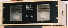
Here's the Clair Brothers. 🙂
/Hugo
thats the one i had 😀 them pretty led's 😀
Someone sent me a mail re. the layout posted. I managed to delete it instead of answering.
Here it is: Layout is from 700B. Schematic post #36.
/Hugo 🙂
Here it is: Layout is from 700B. Schematic post #36.
/Hugo 🙂
pinkmouse said:
Did Clair Bros split out the transformers to make them more roadworthy like Brit Row did?
I don't think so. The main feature is the steel chassis and some large power resisters on the output as part of a stability network.
I was quite pleased with the amp and sold it to a friend who is a small sound guy because he was quite impressed with it.
About 2 years later I bought it back off him for what I paid and what I sold it to him for $700. The about 2 years after that I advertised it in the Local Trading Post and a Phase Linear guru bought it the same evening the advert went to press for $700.
Attachments
Did Clair Bros split out the transformers to make them more roadworthy like Brit Row did?
Not sure What Clair Brothers did. However, when I was in the business we repalced one of the the transformer bolts with a longer one and the bolt then fit into a bracket in the rack. It supported the amp fine.
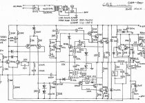
I've looked at the PL 700 schematic in the past and I have a few comments.
Two cascaded diff amps can be seen at the input, the first has no emitter degeneration, the second has heavy degeneration.
The VAS stage does not have a Cdom cap, instead it has RC compensation at the base, and an RC to ground at the collector:
http://www.diyaudio.com/forums/showthread.php?postid=548640#post548640
A cap provides HF feedback from the VAS to the diff amp.
There are three voltage gain stages, and this can be difficult to compensate.
It seems that this amp does not follow good design practice based on what we know today. I have to wonder how stable the original was and if it would be stable with modern replacement semis.
I would say that stability analysis would be required with new semis.
If new semis are used it makes sense to make the output stage complementary if the quasi version can be made stable then both sides have to work and then there is no reason not to go complementary. The CFP side usually provides much more current into low Z loads.
I would consider removing one diff amp stage.
If both are retained I'd consider heavy degeneration in the first stage and less in the second as can be seen in Otala's design, also see:
http://www.diyaudio.com/forums/showthread.php?postid=548259#post548259
Consider a matched pair in the diff amp, and a current source for the emitters.
Big modern output devices should have significantly greater SOA and it should be possible to eliminate the output current limiting, fuses would be wise, and calculations to confirm this idea.
I'd say a full redesign would be best, wish I had the time.
What I described is fairly close to a supersized Adcom.
Pete B.
Member
Joined 2002
Does some one have the full schematic for the bar led display im talking about ? Id like to build one..
J'
J'
jleaman said:Does some one have the full schematic for the bar led display im talking about ? Id like to build one..
J'
I've got the schematic (PDF) as part of the entire manual. I've repaired several due to an aging coupling cap. The leds were in a dip and is likely obsolete. There may be other chips that are obsolete. It's actually a pretty complicated circuit as it compresses the signal to display the dynamic range. email me if you want the manual.
Hi Hugo,
Does look like much was copied, do you know which came first?
Interesting.
What I worry about is if the original was all that stable, have to wonder about reactive loads? Then rebuilding it and perhaps making the stability even worse that's a concern.
Perhaps a properly sized Cdom cap and a carefully placed zero in the second diff amp should be considered if one wanted to keep it as close as possible to the original.
Pete B.
Netlist said:Pete,
Thanks for your post. I found a similar design from the ‘old days’ by C-Audio (?).
It sheds a light on how things were done (or copied) in these days.
/Hugo
PB2 said:Cdom cap and a carefully placed zero in the second diff amp
Care to explain some more or draw a little schematic?
I understand the second diff amp but that’s about it. 🙂
It would sure be nice to work as close as possible to the original.
Also, I have no idea who came first.
/Hugo
Let me mention that I'd add degeneration to the first stage, and probably less to the second.
The compensation that I'm talking about is C2 in this schematic of Otala's design:
http://www.diyaudio.com/forums/attachment.php?postid=553320&stamp=1105870798
I write a bit more about in the last paragraph here:
http://www.diyaudio.com/forums/showthread.php?postid=556106#post556106
I've not seen the insides of a PL-700 how are the output devices wired, long or short interconnects?
Pete B.
Netlist said:
Care to explain some more or draw a little schematic?
I understand the second diff amp but that’s about it. 🙂
It would sure be nice to work as close as possible to the original.
Also, I have no idea who came first.
/Hugo
Member
Joined 2002
d3imlay said:
I've got the schematic (PDF) as part of the entire manual. I've repaired several due to an aging coupling cap. The leds were in a dip and is likely obsolete. There may be other chips that are obsolete. It's actually a pretty complicated circuit as it compresses the signal to display the dynamic range. email me if you want the manual.
I' can still get dip style led array's. But i still would like the schematic too. 😛 please.
you can email it to jase @ jaessspace.com
Thanks
J'
I did not intend to kill this thread, just offer a few suggestions.
The experience of others is helpful here and perhaps someone
will do some stability analysis either in simulation or on a test
unit, really both should be done.
The output devices were rather high voltage for their day, AC
Delco parts I believe. Does anyone know if these are similar
to 2N3773s or any other device that might be used for simulation
of the original. I read somewhere that the output devices were
selected for low beta, which seems odd.
Anyone know the low freq open loop gain of this amp?
This is an interesting amp, and part of audio history, hope you
all continue.
Pete B.
PB2 said:Hi Hugo,
Does look like much was copied, do you know which came first?
Interesting.
What I worry about is if the original was all that stable, have to wonder about reactive loads? Then rebuilding it and perhaps making the stability even worse that's a concern.
Perhaps a properly sized Cdom cap and a carefully placed zero in the second diff amp should be considered if one wanted to keep it as close as possible to the original.
Pete B.
PB2 said:Let me mention that I'd add degeneration to the first stage, and probably less to the second.
The compensation that I'm talking about is C2 in this schematic of Otala's design:
http://www.diyaudio.com/forums/attachment.php?postid=553320&stamp=1105870798
I write a bit more about in the last paragraph here:
http://www.diyaudio.com/forums/showthread.php?postid=556106#post556106
I've not seen the insides of a PL-700 how are the output devices wired, long or short interconnects?
Pete B.
Pete,
I was the one who should have replied. 🙂
Unfortunately, I can only thank you for the detailed explanation you gave. I don't have the time nor the brains for math.
Anyway, for those who want to tackle this project, I can do some measurements on my rebuild specimen if required.
I can also tell that the wiring was done pretty short in the original design; that is from driver board to output transistors.
I used MAT02 in the first diff pair and substituted it with no other alterations. I believe this is still a good transistor pair but it might be obsolete.
As for the output devices, good replacements are listed somewhere in d3imlay's pdf's.
/Hugo
I as well hope that this thread continues. The Phase Linear Lynnwood web site lists ON Semi MJ21195/96 as the highest SOA output transistor that they recommend for replacements of originals. I have used these as replacements already in one of my 700's.
I have downloaded some PCB software and will use Netlist's PCB image file to recreate the original board and plan to have two made for my own use. It's a 30 day trial on the software and hopefully I can get this done with current schedule.
I am not of sufficient knowledge to contribute to improvements to design but I can help with posting any pictures of original amp internals or posting scans of the service manual.
Also,
Please explain which transistors are the diff. pair?
Take care,
I have downloaded some PCB software and will use Netlist's PCB image file to recreate the original board and plan to have two made for my own use. It's a 30 day trial on the software and hopefully I can get this done with current schedule.
I am not of sufficient knowledge to contribute to improvements to design but I can help with posting any pictures of original amp internals or posting scans of the service manual.
Also,
I used MAT02 in the first diff pair
Please explain which transistors are the diff. pair?
Take care,
The first diff pair is Q1 and Q2, both TIS97 on one of the schematics. Second one is Q3 and Q4 which I substituted with BF493.
/Hugo
/Hugo
Different schematics
I agree that it is best to do the earlier version without the OP amp, but there seem to be several schematics.
The version with the MPS5172 transistors in the first diff amp seems to be the earlier version. This is designated as the PCB-14A schematic. It is hard to believe that they run the diff pair straight off the +/-100 V rails. The collector and emitter resistors are so large that they drop a lot of volts and set a fairly low operating current, perhaps keeping them safe.
The +/- 100V supply is risky which probably lead to the next version with the TIS97 input diff pair where the B+ is zener regulated down to +2?V (can't read the schematic) and it also supplies the second diff pair. This is good, a much more reasonable voltage, and these stages do not need a large supply since they're not required to swing the full output voltage. The negative supply is resistor divided down to 1/4 of the main supply, don't know why he cheaped out here, could have used another zener.
I agree that it would be good to use a dual pair transistor in the diff amp(s). It is tempting to borrow the front end of the JE-990 op amp in order to bring this amp more up to date. I also agree with using the ON Semi MJ21195/96 transistors for outputs.
Pete B.
- Status
- Not open for further replies.
- Home
- Amplifiers
- Solid State
- Phase Linear Model 700