I am new to diy audio and are interested in building a pair of diy bookshelf speakers using the SB Acoustics SB26ST-C000-5 and SB Acoustics SB13PFC25-04.
I know phase on your x over are important but do you need to know the drivers phase (manufacturers like dayton audio shows a phase graph while most dont) to propperly design a x over? in other words, how important are the drivers phase durin x over design?
I know phase on your x over are important but do you need to know the drivers phase (manufacturers like dayton audio shows a phase graph while most dont) to propperly design a x over? in other words, how important are the drivers phase durin x over design?
You'll learn that during measurements. Phase is derivable from the frequency response chart.
In terms of absolute phase, all drivers should push towards the listener when a + battery terminal is attached to the + side.
In terms of absolute phase, all drivers should push towards the listener when a + battery terminal is attached to the + side.

You'll learn that during measurements. Phase is derivable from the frequency response chart.
I Don’t have any measurement equipment other than a marantz measuring mic which i know dont give verry acurate results if that was what you ment by ” You'll learn that during measurements.” and how do you derive phase from the frequency response chart?
Hey Eha,
Were you planning on making your crossovers without measurements??
It's math, but the phase is related to the derivative of the frequency response, or something like that. What it means is that your measurement tool like Room EQ Wizard or OmniMic or whatever you use will create a phase plot for you.
Best,
E
As said above all speakers should go forward with same signal polarity.
After that phase gets complicated. The closer the speakers which are in phase the less the combing effect.
Speakers which are far apart and the listener is closer to one than the other can get interphase shift effects.
After that phase gets complicated. The closer the speakers which are in phase the less the combing effect.
Speakers which are far apart and the listener is closer to one than the other can get interphase shift effects.
This should be OK with a manufacturers response but I wouldn't use it on a speaker in a box.Phase is derivable from the frequency response chart.
i tried to measure my current speakers (naim n-sat) phase curve and it came out like in the picture. would a phase curve looking like that be adequate for designing a decent x over (dont have to be perfect by any means), i just dont see a resemblance to the mesurments dayton audio gives out on their drivers.
Attachments
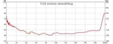
At 20 Hz phase changes after 17m*
At 20 kHz phase rotation happens every 1.7 cm
There are reflections and bouncing ( luckily sound extinguishes after a while) in a room
What's the point?
*
the "negative side" is at half lambda, so 8.5 m 😱
At 20 kHz phase rotation happens every 1.7 cm
There are reflections and bouncing ( luckily sound extinguishes after a while) in a room
What's the point?
*
the "negative side" is at half lambda, so 8.5 m 😱
Study the datasheet for the smaller SB21SDC-4 soft dome tweeter. You might favor the high frequency polar response with a 2,000+ Hz crossover, and the smaller diameter allows a shorter C-to-C distance.
You can also search for a completed design to study and compare your simulation data to prove your understanding and method before you purchase drivers and L-R-C parts.
You can also search for a completed design to study and compare your simulation data to prove your understanding and method before you purchase drivers and L-R-C parts.
I would not rely on frequency response or phase response measured in the datasheet to design the crossover.
The datasheet info is useful for selecting appropriate drivers maybe, but you're far better off measuring the drivers you have in the finished enclosure with an inexpensive microphone like a MiniDSP UMIK-1 or Dayton UMM-6. This is because there are often variations in manufacturing of drivers that causes their response to deviate from the datasheet, and because you don't know if the phase info in the datasheet has a delay/offset. The main purpose of the frequency response in the datasheet is to show that the driver does or doesn't have major defects at certain frequencies.
What the phase of each driver is doing is not really important. What is important is to design the crossover such that the overall phase (driver + crossover) is aligned at the crossover frequency. Say you have a woofer and tweeter and want to cross them at 2kHz, then they should both have the same phase (no matter what the absolute value is) at 2kHz after you've added the highpass and lowpass filters. Ideally you also want them the phase to 'track' for at least an octave above and below this (1kHz to 4kHz). Does not mean that the phase has to be constant from 1-4kHz, just the same on both drivers. If they are both +60degrees at 1Khz, -10degrees at 2kHz and -80degrees at 4kHz, great! If you do this then you have a speaker which delivers more or less the same frequency response on the design axis and to a reasonable angle off axis in either direction. If you have poor phase alignment/tracking, you will have a speaker which achieves flat response on the design axis, but has a peak off axis in one direction and a null in the other off-axis direction - i.e. if you designed you speaker for a sitting position then when you stand up you either get blasted with a peak at 2kHz, or the response droops hard at 2kHz.
There are methods of designing multi-way speakers such that the phase of the finished speaker is more or less constant over the entire frequency range ('linear phase', like your naim n-sat), often purposely maligning the phase of the two drivers, but I would not worry about achieving this for your first speaker design. A beginner is going to achieve far better results just aiming to get drivers aligned at the crossover point. The audibility of the overall phase response of a speaker system is largely debated. Phase misalignment between drivers on the other hand is definitely audible as the frequency response can change dramatically versus listening position in the case of poor phase alignment.
Last edited:
All good advice, IMO. 😎Study the datasheet for the smaller SB21SDC-4 soft dome tweeter. You might favor the high frequency polar response with a 2,000+ Hz crossover, and the smaller diameter allows a shorter C-to-C distance.
You can also search for a completed design to study and compare your simulation data to prove your understanding and method before you purchase drivers and L-R-C parts.
The 5" plastic bass plus 3/4" to 1" tweeter has an illustrious history:
Here an Epos ELS-3:
A tested design using the 5" SB13PFC25-4 is this:
YouTube
Cute little speaker, IMO. Sort of thing you'll have a bit of fun with, albeit here using a compact Vifa ring-radiator tweeter rather than an SB26ST-C000-5 one.
As to phase, Ryan of Impulse Audio has more of a grasp of it than most folks. It's all mathematical in the end, and mathematics is not everybody's strength. Point is, as I often say, "Why reinvent the Wheel", if an experienced somebody has done it before you, try it their way first. Maybe I'm lazy. 😀
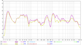
Thanks TMM for that response, it cleard up alot of things but i cant se how spending 120$ (the price for a calibrated mic in sweden) for a mic can add value on a project that cost 100$ in drivers. i looked upp a comparison between a audyssey mic and a calibrated mic and the results are in the picture below.
Attachments
I Don’t have any measurement equipment other than a marantz measuring mic which i know dont give verry acurate results if that was what you ment by ” You'll learn that during measurements.” and how do you derive phase from the frequency response chart?
Then, either:
1. BUY a decent measurement mic and download and LEARN to use proper measurement software (REW, HolmImpulse, etc. are free)
or:
2. STICK to the letter to a well-regarded "kit".
Anything else is a recipe for frustration AND objectively poor results.
M.
Thanks TMM for that response, it cleard up alot of things but i cant se how spending 120$ (the price for a calibrated mic in sweden) for a mic can add value on a project that cost 100$ in drivers. i looked upp a comparison between a audyssey mic and a calibrated mic and the results are in the picture below.
Here's how: in the end it'll be the difference between a 100$ pile of junk, and the best sounding 220$ speakers you have ever heard, possibly rivalling >2k$ commercial speakers if done right.
Which would you rather end up with?
(Of course, it won't be the mic alone. It will MOSTLY be the TIME spent LEARNING how to take and interpret meaningful measurements. On that, I cannot recommend Joe D'Appolito's book highly enough. And there you are: 40$ more... or 30$ if you choose to buy used).
Eha,
there is an alternative to buying ready made measurement mic's. Get a Monacor mce-4001 microphone cartridge, solder a pair of wires to its terminal, fit the cartridge to a pencil body, finish the other end with an rca socket and fill the pencil cavity with cotton wool. These kind of mics need phantom power supply of 9Vdc that you can make of a battery and a few components.
there is an alternative to buying ready made measurement mic's. Get a Monacor mce-4001 microphone cartridge, solder a pair of wires to its terminal, fit the cartridge to a pencil body, finish the other end with an rca socket and fill the pencil cavity with cotton wool. These kind of mics need phantom power supply of 9Vdc that you can make of a battery and a few components.
The closer the speakers which are in phase the less the combing effect.
Ideally the centre-to-centre distance is less than a 1/4 wavelength at the XO. Unless a coax, this is usually not acheivable with a typical cone/dome box.
dave
Phase of each driver is important because it is used to calculate how a crossover will cause your drivers to sum. However, phase on a data sheet is irrelevant for crossover work. There are basically three different ways you can get meaningful phase information for crossover work:
1) Measured phase in cabinet for each driver taken at the same mic location, or
2) Extracted minimum phase from your frequency response measurements in the same setup as 1, or
3) Extracting minimum phase from simulated on baffle frequency response measurements
1) Measured phase in cabinet for each driver taken at the same mic location, or
2) Extracted minimum phase from your frequency response measurements in the same setup as 1, or
3) Extracting minimum phase from simulated on baffle frequency response measurements
Eha,
there is an alternative to buying ready made measurement mic's. Get a Monacor mce-4001 microphone cartridge, solder a pair of wires to its terminal, fit the cartridge to a pencil body, finish the other end with an rca socket and fill the pencil cavity with cotton wool. These kind of mics need phantom power supply of 9Vdc that you can make of a battery and a few components.
I would not do that, i bought ten of those some year ago and all measured way out of specs
- Home
- Loudspeakers
- Multi-Way
- phase importance on drivers