Ok, I think I have the diode correct nowWell I wouldn't use diodes that way. I'd put one from drain to ground, anode on ground side. Thus the FET is protected from reverse voltage.
I guess what I'm thinking about is the fact that I'm only passing voltage thru the primary in one direction, but I see your point, the secondary is still producing an alternating voltage.The value to use for C in the calculation is the series combination of the two tuning capacitors; in your case that would be .005 microfarad. And no, the transformer wouldn't be giving half wave. Transformers can't do that.
Ok, with current values, I have approx 75kHz frequency and a Z of a little over 200K.When I spoke of voltage rating of the transformer I meant the volt-second rating. In other words, you don't want to saturate the core. Raising the voltage or lowering the frequency increase flux density.
The Z value for the tuned circuit probably should be in the range of thousands of Ohms. Making those two capacitors equal does create a large amount of feedback; you probably don't need that much. So make them unequal, with C5 being the larger value.
Well, your help is greatly appreciated as I stumble thru this. Maybe if I could find a good reference, I'd have less difficulty.Keep this up and I will start to charge consulting fees...
Thanks again for your help and I hope I am finally getting close. I am still not sure I have the source resistor sized right and I'm not sure how to determine the total current draw on the primary side.
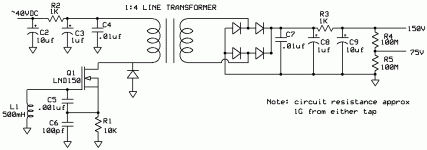
Attachments
Doesn't look bad. You might think about a parallel resonant capacitor across the transformer winding, maybe the secondary, but just think about it. Try the circuit without it and see what you get.
Not sure what to think about R1. Might work better with a big choke there instead. But try it and see.
Not sure what to think about R1. Might work better with a big choke there instead. But try it and see.
Not clear, the Yeti manual says 3-14mm capsules chances are they are electrets since, they are small and multi-pattern big ones are usually two diaphragms on one capsule .
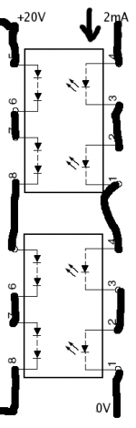
BTW you can stack Vishay VO1263's and get 20V @ 1uA from each for 1mA @ 1.3V in (LED drive). Thought of it but then found an EDN design idea from 1996. No oscillator no fuss. Totally isolated so you can add it on top of the existing voltage easily.
Can you elaborate? I'm not quite following your suggestion. A schematic or reference to how this is done would be helpful. I'm definitely interested in different ways to get somewhere around 150VDC in the 1uA range from a 40VDC 2mA source.BTW you can stack Vishay VO1263's and get 20V @ 1uA from each for 1mA @ 1.3V in (LED drive). Thought of it but then found an EDN design idea from 1996. No oscillator no fuss. Totally isolated so you can add it on top of the existing voltage easily.
BTW, many of the usb mics are large diaphragm, look at more than just the Yeti and multi pattern or not, the 5V from the usb isn't enough to make them work so there has to be some sort of voltage multiplier in use.
Just keep stacking them and stick the low end on whatever is left of your 40V. No need for those 100M loads, G Ohm bias resistor will do nothing once the capsule is charged up. You might want to put a small cap on the end of the chain to filter. I put 40V in an Octava and no one could tell the difference in the sound.
EDIT - BTW you can series parallel for infinite variations. The LED's paralleled would run on 2-AA cells
EDIT - BTW you can series parallel for infinite variations. The LED's paralleled would run on 2-AA cells
Attachments
Last edited:
I don't think there are may ways to get higher performance than that.
Cost performance trade off at $3.5 or so each might be a consideration. Sorry my bad that's 40V ($7) up there (what I put in the Octava).
Scott! WOW! I finally see the light (well, not really, I imagine the LED is sealed up so I can't see it) I could stack a dozen or so of these running a about a mA and get exactly what I want when my load is only 1G.
I do have a question now. What's a good and fairly accurate way to measure my output voltage when my current draw is in nA?
I do have a question now. What's a good and fairly accurate way to measure my output voltage when my current draw is in nA?
Scott! WOW! I finally see the light (well, not really, I imagine the LED is sealed up so I can't see it) I could stack a dozen or so of these running a about a mA and get exactly what I want when my load is only 1G.
I do have a question now. What's a good and fairly accurate way to measure my output voltage when my current draw is in nA?
I forgot to mention they are duals so you only need 6. If you have a 10Meg input VOM just series the 1G and read X100. I have an electrometer but that is not normal lab equipment. You are essentially using it unloaded and get the open circuit voltage, you get 5 volts out at 11uA!
It looks like the LH1262CB gives good no load voltage even down to 1mA on the LED. $3.06 each when I order 10 from Mouser. A bit of a cost, but still not too bad.
Not sure I follow what you mean with the 1G in series with my 10Meg input VOM. Can you draw a quick sketch? Maybe I shouldn't worry about it and just hook it up and to the mic capsule and see what happens. This so greatly reduces the complexity.
Thank you Scott.
Not sure I follow what you mean with the 1G in series with my 10Meg input VOM. Can you draw a quick sketch? Maybe I shouldn't worry about it and just hook it up and to the mic capsule and see what happens. This so greatly reduces the complexity.
Thank you Scott.
It looks like the LH1262CB gives good no load voltage even down to 1mA on the LED. $3.06 each when I order 10 from Mouser. A bit of a cost, but still not too bad.
Not sure I follow what you mean with the 1G in series with my 10Meg input VOM. Can you draw a quick sketch? Maybe I shouldn't worry about it and just hook it up and to the mic capsule and see what happens. This so greatly reduces the complexity.
Thank you Scott.
Those graphs are pretty bad at the low end. From my measurements they have a "gain" ~1uA per mA that is linear down to 100-200uA of LED current or better. I just meant that you could make a 100 to 1 divider with 1000M and 10M, it's just that your meter has an input resistance. My little Beckman is 1M so I guess you could read 1mV as 1V on it. I was thinking of an HP lab meter they are 10M.
For testing purposes, I can use a 100K and 1G series and measure voltage across the 100K and scale up. That will be pretty close to no load measurement. I'll have to get a few of these and breadboard a circuit to see how low a current I can feed the LED's and still get the voltage I want.
That VO1263 is a pretty good part for this. Use as much current as you have availble, anything to stay off the linear region without overloading the supply or putting life on the LEDs. A few mA. If it's not a battery who cares about power. A better part would show higher voltage and "saturation" at lower current with heavier loads. I didn't see any. Some low leakage capacitor on the output and you're running. You could get fancier but why if it wont help. No switching or oscillator is nice for low noise.
I want to power this with phantom power off a mix board and it's got the usually 6.81K supply resistors which don't provide much current if I want to still have 25 or 30V to play with on other parts of my circuit. The current draw on the multiplied side is almost nothing so I'll experiment and see what I get. I can probably push 1.5mA to the LED's before I suck too much from the rest of my circuit.Use as much current as you have availble, anything to stay off the linear region without overloading the supply or putting life on the LEDs. A few mA.
Well I suppose for higher power efficiency you could series parallel some but the price goes up fast.
Last edited:
I really think 4 or 5 chips strung together is going to do exactly what I need when supplied with 1 to 1.5 mA
Hey bob91343, while I will probably try the photocell route at least to start with for this particular project, I am still very interested in various methods of dc - dc conversion and I may still try the collpit oscilator and transformer just to satisfy my curiosity. Thanks again for all your help. The DIY Forum is awesome!
- Status
- Not open for further replies.
- Home
- Source & Line
- Analogue Source
- phantom voltage multiplier