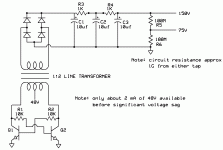
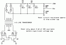
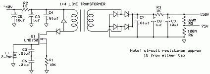
I'm wanting to put higher voltage on a mic diaphragm as well as provide ability to center supply for figure of 8 pattern on dual diaphragm mics. Will this circuit work? What transistors would you suggest? I know the final output side current draw is almost negligible but how do I calculate the losses to determine supply current draw?
Attachments
Obviously the base resistors will have 96 V so that gives the loss in the base resistors. The loss in the transistors will be small. The transformer core is really the unknown. I assume, due to the lack of a resonating capacitor, you are relying on saturation of the core to determine frequency. So that is the main unknown.
Incidentally, you offer no protection for the reverse voltage on the bases, so they will break down when that side goes negative. You should do something about that.
Incidentally, you offer no protection for the reverse voltage on the bases, so they will break down when that side goes negative. You should do something about that.
Yes, the transformer saturation would determine the frequency, how would a resonating cap be tied into the circuit?Obviously the base resistors will have 96 V so that gives the loss in the base resistors. The loss in the transistors will be small. The transformer core is really the unknown. I assume, due to the lack of a resonating capacitor, you are relying on saturation of the core to determine frequency. So that is the main unknown.
Would the diodes solve that? I changed the resistors to 47K because 10K would suck too much current. Also, how do you figure 96V on the resistor with a 48V supply?Incidentally, you offer no protection for the reverse voltage on the bases, so they will break down when that side goes negative. You should do something about that.
Attachments
When the left hand transistor conducts and the left side of the winding is thus grounded, the right side, due to transformer action, will soar to double the supply voltage, or 96 V.
The diodes are in the wrong place. They should be in anti parallel with the base-emitter junctions. A resonating capacitor would be across the winding.
Frankly, this is not a circuit for the casual designer. Many years ago I designed many like it and you need a square loop core material to minimize losses and help define the square waveform. So the best would be to wind your own. You may need speedup capacitors across the base resistors. Furthermore, the transistors experience high voltage in the off state and must be capable of withstanding that.
Perhaps you should reconsider and use a Colpitts or Hartley oscillator. Or even a relaxation oscillator (flyback).
Last edited:
can you point me to a book or article that discusses this? The high voltage current draw is so tiny but I want the voltage in the 150V or so range. And I don't have much 48V current to start with.Perhaps you should reconsider and use a Colpitts or Hartley oscillator. Or even a relaxation oscillator (flyback).
Just Google the terms. Or consult any basic electronics textbook. These are classic circuits and have been around since before I was born, and I am old. Originally of course they used tubes but all the rules apply to solid state.
A flyback circuit is often used for photoflash use. And you will find them in modern switching power supplies as well.
I also suggest you operate above the audio range or you may find the noise will get into your system. And will radiate to other circuits, so it should be carefully filtered and shielded. You show no filtering on the primary side, but it's important.
I'm wanting to put this inside the mic body so it has to be small, you mention flyback but are there flyback transformers small enough and wound for about a 4X increase? How do I use a flyback in a manner that sets the frequency above 30kHz or so to be above audio? and how do I filter and shield this from the rest of the 48V circuit?Just Google the terms. Or consult any basic electronics textbook. These are classic circuits and have been around since before I was born, and I am old. Originally of course they used tubes but all the rules apply to solid state.
A flyback circuit is often used for photoflash use. And you will find them in modern switching power supplies as well.
I also suggest you operate above the audio range or you may find the noise will get into your system. And will radiate to other circuits, so it should be carefully filtered and shielded. You show no filtering on the primary side, but it's important.
Maybe I'm dreaming thinking I can accomplish this feat but I'm sure there are usb mics that do something simliar.
Here's several that are usb with externally polarized capsules.Are there any USB mics with externally polarized capsules? The files section at the Yahoo micbuilders group has several schematics some from commercial mics.
USB Mics | Sweetwater.com
There are no inherent size limitations to flyback transformers. The size of a transformer is largely dictated by the amount of power it has to handle and its frequency of operation; whether it's flyback, saturating, or anything else has only a minor effect on size.
Really, you are asking for major design help here and you should either find one that's already designed or figure out how to do it. It's not rocket science but takes time and patience and information to take care of the details. Not to speak of the parts procurement and testing.
As for shielding, that's yet another topic. If you don't shield it well enough, it will interfere with other electronic circuits. And the conduction to associated components may cause problems too.
Where do I go to figure this out? I'm only looking for about 1 micro amp of power, that's .000001 amps of power. I don't see how a tiny line transformer could be even close to overworked. I just need to keep the supply side from drawing too much current. A resonance capacitor was mentioned but I'm not finding anything on what size cap I should use to get the frequency up to where I would like it. Does anyone know if there are flyback transformers this tiny available off the shelf? I don't mind doing some figuring out on my own but I'm having a hard time finding resources when I search the net. It seems everyone using flybacks are doing spark gap, plasma globes and things like that. I only need 150V.There are no inherent size limitations to flyback transformers. The size of a transformer is largely dictated by the amount of power it has to handle and its frequency of operation; whether it's flyback, saturating, or anything else has only a minor effect on size.
Really, you are asking for major design help here and you should either find one that's already designed or figure out how to do it. It's not rocket science but takes time and patience and information to take care of the details. Not to speak of the parts procurement and testing.
As for shielding, that's yet another topic. If you don't shield it well enough, it will interfere with other electronic circuits. And the conduction to associated components may cause problems too.
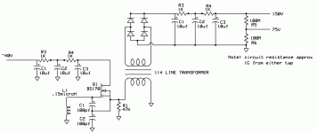
OK, here is basically a guess at a Colpitts oscillator for dc dc conversion. From previous experiments, I'm probably only going to have 35 to 40 volts available even though they claim 48V phantom power. I've chosen the BS170 because I've used them before at these voltages and I have a lot in stock. The RC filters are mainly to keep the oscillator from affecting the other circuits attached to the same power supply. If you know better ways to do this, let me know.
Please feel free to throw stones at this as I'm doubtful that it's correct.
Please feel free to throw stones at this as I'm doubtful that it's correct.
Attachments
You have L1 in parallel with the output transformer. Shouldn't the latter be in the drain circuit? Of course some protection for the FET would be appropriate, due to the inductance of the primary. What function does R1 serve? You would need it if the transformer were put into the drain circuit.
I didn't calculate the frequency; I guess it's well above audio range. Perhaps right on the same frequency with some local broadcast station...
I assume the FET is depletion mode, else the oscillator wouldn't start.
I didn't calculate the frequency; I guess it's well above audio range. Perhaps right on the same frequency with some local broadcast station...
I assume the FET is depletion mode, else the oscillator wouldn't start.
I think it's around 50MHz, what should I aim for?You have L1 in parallel with the output transformer. Shouldn't the latter be in the drain circuit? Of course some protection for the FET would be appropriate, due to the inductance of the primary. What function does R1 serve? You would need it if the transformer were put into the drain circuit.
I didn't calculate the frequency; I guess it's well above audio range. Perhaps right on the same frequency with some local broadcast station...
I assume the FET is depletion mode, else the oscillator wouldn't start.
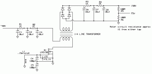
Does the added diode provide proper protction for the MOSFET?
I changed to an LND150 which is a depletion mode. I have used them often and have several in stock.
Have I moved the transformer to the proper location now?
Thanks for your help.
Attachments
The diode won't protect against high voltage spikes on the drain. Further, the frequency is way too high for any normal transformer; I'd shoot for maybe 50-100 kHz. Plus, make sure the transformer can withstand the high voltages you are applying. In addition, C3 is electrolytic and needs to be bypassed by a paper or ceramic capacitor to be effective at these frequencies. And the rectifiers need to be fast ones.
You may also want to resonate the transformer at the operating frequency; add a capacitor in parallel with the winding.
Any further development of this circuit requires a breadboard or, at the very least, a simulation.
You may also want to resonate the transformer at the operating frequency; add a capacitor in parallel with the winding.
Any further development of this circuit requires a breadboard or, at the very least, a simulation.
Ok, does ZD2 protect the spikes to the drain now? I've added film caps on both the input and output filters to take the high frequency out. Also, I've changed the inductor and caps to get the frequency more in line.The diode won't protect against high voltage spikes on the drain. Further, the frequency is way too high for any normal transformer; I'd shoot for maybe 50-100 kHz. Plus, make sure the transformer can withstand the high voltages you are applying. In addition, C3 is electrolytic and needs to be bypassed by a paper or ceramic capacitor to be effective at these frequencies. And the rectifiers need to be fast ones.
You may also want to resonate the transformer at the operating frequency; add a capacitor in parallel with the winding.
Any further development of this circuit requires a breadboard or, at the very least, a simulation.
Does this look close enough to breadboard now?
Attachments
Nope. You have the bottom capacitor shorted. I can't say if ZD1 will protect or, for that matter, allow oscillation. Further, ZD2 isn't too good an idea, as it may screw up the oscillation - it will conduct on every half cycle. If you want to do it that way I'd use 80V not 40V. I would suggest a diode across the transformer primary, instead, and another to prevent negative on the drain. Incidentally, this transformer will be carrying dc so should be designed for that.
I didn't compute the impedance of your resonant circuit. That would be square root of L/C and should be fairly high, since we are driving a high impedance gate.
I didn't compute the impedance of your resonant circuit. That would be square root of L/C and should be fairly high, since we are driving a high impedance gate.
DOH oops. Ok so how do I size the source resistor?Nope. You have the bottom capacitor shorted.
I'm looking at a Tamara transformer that has a dielectric strength exceeding 1000V and although this isn't what it's designed for, this will be such low current and I am willing to give it a try.I can't say if ZD1 will protect or, for that matter, allow oscillation. Further, ZD2 isn't too good an idea, as it may screw up the oscillation - it will conduct on every half cycle. If you want to do it that way I'd use 80V not 40V. I would suggest a diode across the transformer primary, instead, and another to prevent negative on the drain. Incidentally, this transformer will be carrying dc so should be designed for that.
I didn't compute the impedance of your resonant circuit. That would be square root of L/C and should be fairly high, since we are driving a high impedance gate.
http://www.tamuracorp.com/clientuploads/pdfs/engineeringdocs/TTC-108N.pdf
Here's the inductor I'm considering:
http://www.mouser.com/catalog/specsheets/114308.pdf
Do I have the diode arrangement correct finally?
I realize that the secondary will only be seeing half wave but I have a full wave rectifier, I don't see that as a problem do you?
When calculating impedance, what do I use for the C value?
.0022/.00000001 = 469, this seems low, is this correct? do I need to change my L/C ratio to make this higher?
Attachments
Well I wouldn't use diodes that way. I'd put one from drain to ground, anode on ground side. Thus the FET is protected from reverse voltage.
The value to use for C in the calculation is the series combination of the two tuning capacitors; in your case that would be .005 microfarad. And no, the transformer wouldn't be giving half wave. Transformers can't do that.
When I spoke of voltage rating of the transformer I meant the volt-second rating. In other words, you don't want to saturate the core. Raising the voltage or lowering the frequency increase flux density.
The Z value for the tuned circuit probably should be in the range of thousands of Ohms. Making those two capacitors equal does create a large amount of feedback; you probably don't need that much. So make them unequal, with C5 being the larger value.
Keep this up and I will start to charge consulting fees...
- Status
- This old topic is closed. If you want to reopen this topic, contact a moderator using the "Report Post" button.
- Home
- Source & Line
- Analogue Source
- phantom voltage multiplier
