Hi
That is probably because it is pretty simple to understand, but I think I would go for uc, if anything I could get it more easy
That is probably because it is pretty simple to understand, but I think I would go for uc, if anything I could get it more easy
ok
material types. i built a pfc that works pretty well until the current gets up to 2 amps at 320v then i get crazy spikes in current.. well iused the wrong core a ft-240-77 material. oops saturation i think.
i have a 3, 8, and 26, ft-240 cores.
i read that 26 may get to hot at 100khz? i looks as if the inductance and bmax should be ok however?
it is a 320v at 6 amps.........
material types. i built a pfc that works pretty well until the current gets up to 2 amps at 320v then i get crazy spikes in current.. well iused the wrong core a ft-240-77 material. oops
saturation i think.i have a 3, 8, and 26, ft-240 cores.
i read that 26 may get to hot at 100khz? i looks as if the inductance and bmax should be ok however?
it is a 320v at 6 amps.........
Ya' know, I hear conflicting advice on material type for the PFC inductor. Some say ferrite (like the #77 material), and others say powdered-iron (like the #26 stuff). In my experience of doing DC-DC uppies, #26 powdered-iron cores have, by far, worked the best.
My very first DC-DC uppie got real hot when current draw was anything over a few hundred milliamps. I had used an FT-68-77 for the core, with the correspondingly low number turns. I remembered seeing several cell-phone chargers using the yellow-white (#26) toroids for the main buck inductor, so I decided to try it for my ckt. Lo and Behold!, the current ratings were normal, inductor temp stayed reasonably cool (until saturation current was reached), and life became good.
I would extend this same logic and reasoning to the PFC inductor core material choice.
Steve
An ungapped ferrite core will have almost no energy storage capability due to the high permeability so that's pretty expected. 🙂
Is there any way to synchronise this IR chip with master clock frequency.....??
My smps is working at around 125khz, i want to sync PFC also.
My smps is working at around 125khz, i want to sync PFC also.
Workhorse said:Is there any way to synchronise this IR chip with master clock frequency.....??
My smps is working at around 125khz, i want to sync PFC also.
Why do you want to syncronize? Active PFCs usually run at 25-35Khz.
PFC cores
We use Micrometals #8 material as suggested by them. #18 works as well but is more expensive. #26 is useless as the core losses are too high. Our PFCs have to supply upwards of 2.4Kw so core selection is critical
The IR1150s cannot be synchronized with anything else, there is no ramp output just a single resistor for frequency selection.
Running PFC at 25-35KHz will mkae the magnetics very large, and we do not have the space. 100KHz seems to be the best compromise between size, $$ and efficiency.
Steve Mantz
Zed Audio Corp.
Beat frequency whistling might occur if not synched..........🙁
smps and class-d are already synched thru master clock..........PFC is left
smps and class-d are already synched thru master clock..........PFC is left
Re: PFC cores
Steve, if I may ask, where do you get your toroid cores wrapped?
MOER said:We use Micrometals #8 material as suggested by them. #18 works as well but is more expensive. #26 is useless as the core losses are too high. Our PFCs have to supply upwards of 2.4Kw so core selection is critical
The IR1150s cannot be synchronized with anything else, there is no ramp output just a single resistor for frequency selection.
Running PFC at 25-35KHz will mkae the magnetics very large, and we do not have the space. 100KHz seems to be the best compromise between size, $$ and efficiency.
Steve Mantz
Zed Audio Corp.
Steve, if I may ask, where do you get your toroid cores wrapped?
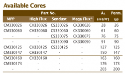
hi all, i have drawn a smps schematic and on the pfc side i am planning to use the onsemi chip ncp1653 . the core i was planning to use the black core cs330060 with about 61 turns.
ideas and comments are highly welcomed.below is the smps schematic and core datasheet 🙂
ideas and comments are highly welcomed.below is the smps schematic and core datasheet 🙂
Attachments
-
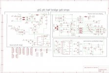 gtG lp smps fb ver 1 dip drive schematic.jpg465.4 KB · Views: 241
 -
gtG lp smps fb ver 1 dip drive schematic.pdf53.2 KB · Views: 163
-
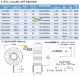 cs330060 0 287a12efcef2fe14.jpg187.2 KB · Views: 239
 -
 Screenshot from 2020-04-09 12-59-54.png32.9 KB · Views: 209
 -
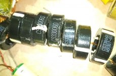 IMG_20200409_003532_659_1586383090241.jpg424.3 KB · Views: 221
- Home
- Amplifiers
- Power Supplies
- PFC inductor advice