🙂In the Heathkit UA-1 12W Amplifier we see a 0.1 microF capacitor bypassing a one Meg resistor supplying the screen current. We might think that we can simply take that RC time constant & easily estimate the low frequency rolloff. But we would be dead wrong & get a result with a gross error.
The actual R the supply resistor is driving into is the screen resistance, analogous to a plate resistance of a triode. So the R in the RC time constant then becomes the parallel resistance of the screen & supply resistances. The problem is complicated by the lack of any published data with regards to screen resistance.
Fred Terman (And Wm. Hewlett) tell us that screen resistance for a pentode can be estimated as follows-
rs = ( ( Ib + Ic2 ) / Ic2 ) * Rp
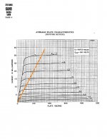
From this we need to know 6AN8 triode connected pentode Rp, another spec not published for the 6AN8. For the attached 6AN8 pentode plate family draw a line from the origin to the intersection of the Ec1 zero bias curve where Ec2 & the plate are at equal voltage. In this example that would be at 150 plate volts.
Triode plate Rp for the pentode section at zero bias is approximately as follows-
Rp ~ Change of Eb / Change of Ib
From the 6AN8 Average Transfer page, Change of Eb = 150 Volts
& Change of Ib ~ 28mA (plate) + 9mA (screen)
So triode Rp ~ ( 150 / 37 ) K or 4.05K
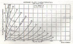
Aside from the scale factors of voltage & current all common triode plate families look very much the same. As an example refer to the 6BQ7 plate family. When G1 bias is increased plate resistance increases. As an educated guess we can assume Rp for a triode connected 6AN8 pentode section to be something like 10K at the operating point.
Using the typical operating currents split on the 6AN8 pentode we get-
rs ~ ( ( 9 + 2.8 ) / 2.8 ) * 12K
or rs ~ 42.1K
That is the number we need to compute the rolloff frequency of the amplifier front end.
The R in the RC calculation now becomes rs in parallel with one M.
So R ~ 40.4 K, a factor of about 20 times different than where we started.
RC = 0.0040 sec F = 0.159 / RC Hz 39.4 Hz
Looks like it is a step built in as part of the NFB stabilization circuits.
Note 1- Wm Hewlett & David Packard of HP were Fred Terman’s Graduate Students at Stanford U.
The actual R the supply resistor is driving into is the screen resistance, analogous to a plate resistance of a triode. So the R in the RC time constant then becomes the parallel resistance of the screen & supply resistances. The problem is complicated by the lack of any published data with regards to screen resistance.
Fred Terman (And Wm. Hewlett) tell us that screen resistance for a pentode can be estimated as follows-
rs = ( ( Ib + Ic2 ) / Ic2 ) * Rp
From this we need to know 6AN8 triode connected pentode Rp, another spec not published for the 6AN8. For the attached 6AN8 pentode plate family draw a line from the origin to the intersection of the Ec1 zero bias curve where Ec2 & the plate are at equal voltage. In this example that would be at 150 plate volts.
Triode plate Rp for the pentode section at zero bias is approximately as follows-
Rp ~ Change of Eb / Change of Ib
From the 6AN8 Average Transfer page, Change of Eb = 150 Volts
& Change of Ib ~ 28mA (plate) + 9mA (screen)
So triode Rp ~ ( 150 / 37 ) K or 4.05K
Aside from the scale factors of voltage & current all common triode plate families look very much the same. As an example refer to the 6BQ7 plate family. When G1 bias is increased plate resistance increases. As an educated guess we can assume Rp for a triode connected 6AN8 pentode section to be something like 10K at the operating point.
Using the typical operating currents split on the 6AN8 pentode we get-
rs ~ ( ( 9 + 2.8 ) / 2.8 ) * 12K
or rs ~ 42.1K
That is the number we need to compute the rolloff frequency of the amplifier front end.
The R in the RC calculation now becomes rs in parallel with one M.
So R ~ 40.4 K, a factor of about 20 times different than where we started.
RC = 0.0040 sec F = 0.159 / RC Hz 39.4 Hz
Looks like it is a step built in as part of the NFB stabilization circuits.
Note 1- Wm Hewlett & David Packard of HP were Fred Terman’s Graduate Students at Stanford U.
Hi John,
Thanks for posting here on diyaudio, over the years, you have posted many great articles and comments on rec.audio.tubes, it will be great if you can re-post some the articles, I'm sure many users will enjoy reading them here.
jaz
Thanks for posting here on diyaudio, over the years, you have posted many great articles and comments on rec.audio.tubes, it will be great if you can re-post some the articles, I'm sure many users will enjoy reading them here.
jaz
John, it seems you have derived an estimate of rs from data that represents constant screen voltage conditions? Perhaps a Norton equivalent is more appropriate?
These attachments did not make it into the original post. My error, forgot to hit the 'upload' key.
More later, I've done the prelims on an actual test to measure rs.
Check me out over at equipment & tools for something on building & testing with a constant current source. Lots of examples of non-linear devices. It is in a PDF, hope it fits.
More later, I've done the prelims on an actual test to measure rs.
Check me out over at equipment & tools for something on building & testing with a constant current source. Lots of examples of non-linear devices. It is in a PDF, hope it fits.
Attachments
If it's related to the topic here it is perfectly fine to post the information to build a test fixture in this thread, or at least provide an actual link to the referenced thread.
Measurement of Screen Resistance
🙂Described is a way of doing the actual rs measurement. I used a 6U8, simply because I had one. And the example has cathode degeneration which would modify the result. But if NFB is brought to that point as it often is the result is very close.
More later.
This method could be used for any pentode or beam tube. Keep in mind we are looking for 'order of magnitude' only. NTL, useful for design purposes.
There is a slight error in the original post text, the guess of Rp for a triode connected 6AN8 pentode section to be something like 12K at the operating point. I'm surprised no one picked that up!
Enjoy & report any errors!
----------------------------------------------------------------------------
When designing or building an ordinary vacuum tube audio amplifier with a pentode front end we can for the most part ignore the screen supply resistance. Simply set it to be in the range of 3-4 times the plate resister & the circuit will perform satisfactorily. As long as the screen resister is adequately bypassed there are no significant problems.
That all changes when the intention is to use NFB. Most folks would assume that the RC time constant is simply the screen resister times the screen bypass capacitor. That can lead to problems since the screen supply resister is actually in parallel with the resistance of the screen grid itself as seen looking into the tube. Some calculations using the available published tube data indicates the screen resistance of common audio voltage amplifier pentodes to be in the range of 40K.
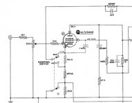
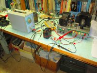
This simple setup makes measurements leading to the incremental screen resistance of the pentode section of a 6U8 vacuum tube while in operation. The tube is connected to a plate supply of 300 volts. The screen is fed from this supply thru a total of 730K resistance. But interposed on that is a means of applying an interfering One KHz test signal. Any audio transformer of high impedance primary & secondary can be used to couple the audio signal generator to the high voltage on the screen. I used an old Hammond 447 IT.
Just two measurements are required. Using a differential probe the AC voltage drop across the 730K is measured, then the AC voltage from common to screen.
The results of two levels of drive voltage are as follows-
First Pass- Drop across 730K was 0.9V
So Ig2 is 0.9 V / 0.73 M, 1.23 mA And Eg2 measured 0.043V
So rs is DE / DI rs = (0.043V / 1.23 mA)K or 35.0K
2nd Pass- Drop across 730K was 2.83V
So Ig2 is 2.83 V / 0.73 M, 3.88 mA And Eg2 measured 0.133V
So rs is DE / DI rs = (0.133V / 3.88 mA)K or 34.3K Done
🙂Described is a way of doing the actual rs measurement. I used a 6U8, simply because I had one. And the example has cathode degeneration which would modify the result. But if NFB is brought to that point as it often is the result is very close.
More later.
This method could be used for any pentode or beam tube. Keep in mind we are looking for 'order of magnitude' only. NTL, useful for design purposes.
There is a slight error in the original post text, the guess of Rp for a triode connected 6AN8 pentode section to be something like 12K at the operating point. I'm surprised no one picked that up!
Enjoy & report any errors!
----------------------------------------------------------------------------
When designing or building an ordinary vacuum tube audio amplifier with a pentode front end we can for the most part ignore the screen supply resistance. Simply set it to be in the range of 3-4 times the plate resister & the circuit will perform satisfactorily. As long as the screen resister is adequately bypassed there are no significant problems.
That all changes when the intention is to use NFB. Most folks would assume that the RC time constant is simply the screen resister times the screen bypass capacitor. That can lead to problems since the screen supply resister is actually in parallel with the resistance of the screen grid itself as seen looking into the tube. Some calculations using the available published tube data indicates the screen resistance of common audio voltage amplifier pentodes to be in the range of 40K.
This simple setup makes measurements leading to the incremental screen resistance of the pentode section of a 6U8 vacuum tube while in operation. The tube is connected to a plate supply of 300 volts. The screen is fed from this supply thru a total of 730K resistance. But interposed on that is a means of applying an interfering One KHz test signal. Any audio transformer of high impedance primary & secondary can be used to couple the audio signal generator to the high voltage on the screen. I used an old Hammond 447 IT.
Just two measurements are required. Using a differential probe the AC voltage drop across the 730K is measured, then the AC voltage from common to screen.
The results of two levels of drive voltage are as follows-
First Pass- Drop across 730K was 0.9V
So Ig2 is 0.9 V / 0.73 M, 1.23 mA And Eg2 measured 0.043V
So rs is DE / DI rs = (0.043V / 1.23 mA)K or 35.0K
2nd Pass- Drop across 730K was 2.83V
So Ig2 is 2.83 V / 0.73 M, 3.88 mA And Eg2 measured 0.133V
So rs is DE / DI rs = (0.133V / 3.88 mA)K or 34.3K Done
Attachments


What impedance does the probe add to the circuit? Do you just move one differential probe around?
Could you grid leak bias the tube, then the cathode could be grounded.
What are the static anode and screen currents relating to the test.
I guess an EF86 would be the most generic candidate tube to get a value for.
Could you grid leak bias the tube, then the cathode could be grounded.
What are the static anode and screen currents relating to the test.
I guess an EF86 would be the most generic candidate tube to get a value for.
Last edited:
Cs Calculation
For some tubes, it is possible to calculate the value of Cs without making measurements, provided that the required parameters are available in the datasheets:
Cs ~ B/(pi*f*Rs), where B = 1 + Rs*gm/mut and m = Ia/Is.
f is the corner frequency and mut is the mu of the pentode when triode-connected. For more details, please refer to RDH4, p. 497.
Thank you for sharing that measurement method!Enjoy & report any errors!
I did spot a couple of minor errors, more on that below.
That would be 1.23 uA**, not mA. However the 35 k value is correct.First Pass- Drop across 730K was 0.9V
So Ig2 is 0.9 V / 0.73 M, 1.23 mA And Eg2 measured 0.043V
So rs is DE / DI rs = (0.043V / 1.23 mA)K or 35.0K
The same error is repeated in the 2nd calculation, the current is 3.88 uA**, and not mA. Once again, the calculated resistance is correct, however.
(** I mean micro amps, of course. I can't figure out how to insert a proper "mu" character into text on this forum.)
Interestingly enough, I encountered this exact problem (i.e., needing to calculate the value of the screen grid decoupling capacitor) just a few days ago.
In my case, the problem arose as part of a guitar preamp design. My initial wild guess at the capacitor value was too big, and this produced blocking distortion when overdriven. So I needed to reduce the cap value, hopefully without compromising bass response too much. But how much could I reduce it?
I couldn't think of an easy way to directly measure the AC impedance at the screen grid, so I hooked up a sine-wave generator and 'scope, and simply measured the lower -3dB corner frequency of the pentode stage with a known, deliberately undersized, capacitor decoupling the screen.
Then I estimated the effective (Thevenin, or Norton if you prefer) resistance at the screen by re-arranging the formula for an RC filter's cut off frequency:
r_screen = 1/(2 pi f3dB C)
With the screen resistance roughly estimated, I could then calculate the appropriate capacitor value using the same RC filter equation, this time substituting in the desired value of f3dB that I wanted:
C = 1/(2 pi r_screen f3dB)
This method, that I came up with and just described, is also an approximate method, particularly since my reference capacitor had a 10% tolerance, and measuring the -3dB corner frequency is not a very precise thing, either.
I do not have a differential AC probe for my 'scope, so this is the only method I can use for the moment.
-Gnobuddy
What impedance does the probe add to the circuit? Do you just move one differential probe around?
I'm using a using a PicoTech MI053 Differential Probe. The load presented to the cct is 4M & should have been included in the calc. In this measurement I used the PicoTech ADC-216, no longer available. It is 16-bit.
The measurement is quite a way off ground, so need lots of care while using these kind of ADCs. The front ends are spec'd only to 20V max, so the probe was set to 1000X.
Could you grid leak bias the tube, then the cathode could be grounded.
Easiest way is simply bypassing the cathode resister with a large value cap. But I guess a separate small battery could also be inserted into the grid lead.
What are the static anode and screen currents relating to the test.
I will have a look next time I hookup. It is finally Spring, lots of manual labor here on the 4.4 Acres!
I guess an EF86 would be the most generic candidate tube to get a value for.
There are quite a few worth looking at. And not difficult.
Cheers
Attachments
Why not just insert a current sampling resistor in the low side of the 1:1 AC injection transformer primary and measure injected AC signal current?
Sampling the current on the primary would include the magnetizing current of the transformer. I wanted to remove as many unknown variables from the test as possible.
Since I have a differential probe that was the best way to a solution for me.
Cheers, John
Since I have a differential probe that was the best way to a solution for me.
Cheers, John
The question was asked-
What are the static anode and screen currents relating to the test.
Here are some numbers
Plate supply was 300V
Plate 56.6V
Screen 32.8V
Cathode 0.72V
Hope that will help.
What are the static anode and screen currents relating to the test.
Here are some numbers
Plate supply was 300V
Plate 56.6V
Screen 32.8V
Cathode 0.72V
Hope that will help.
Most DIYers don't have access to scope probes other than standard voltage probes. Hell, many of 'em don't even have scopes. Perhaps a more universal way to make this measurement/estimate is to simply vary the DC supply voltage to the screen slightly and measure the resulting small current delta. dV / dI = rG2 (dynamic G2 resistance). If the test PSU isn't suitably metered, then a series current-sampling resistor can be inserted. This measurement could even be accomplished by temporarily bridging the screen dropping resistor with a much larger value in-situ and doing a bit more math.
Imho, the test method used by Gnobuddy avoids any doubt, and uses the simplest setup and measurement equipment. Most people have access to 5% tolerance caps, and many have capacitance meters (even the simple cheap testers). Many have access to a voltmeter with a suitably wide rms voltage frequency range, and a suitable sinewave generator (even a $1 soundcard would do). A couple of tests with different caps would give a characteristic plot of -3dB versus capacitance for the nominal operating condition.
Your comments are all too true. Many diys & newbies do not own much at all in the way of test equipment. But still they often spend large on strange & exotic boutique level parts to build the so called ultimate amplifier.
Nor do many have a drawer filled with caps that could be subbed in to get the numbers.
But this kind of measurement is not something most diys or newbies require. It is more for folks like yourselves who obviously know your way around.
As often happens there is more than one way to get the information required. Watch this space for a few daze & there will most likely be another yet!!
And I measured the resulting step to be in the order of 10 db just as Terman sez it to be.
Thanks for the comment. I too like this method because it directly measures the thing we care most about (the frequency response itself).Imho, the test method used by Gnobuddy avoids any doubt, and uses the simplest setup and measurement equipment.
-Gnobuddy
- Status
- Not open for further replies.
- Home
- Amplifiers
- Tubes / Valves
- Pentode Screen Resistance (rs) Estimation Example