Noise in the plate circuit or grid?
Spangenberg gives this for an equivalent resistor in the grid circuit for a noiseless triode (for a pentode model):
Req= 2.5 Ip (1+8 I2/Gm)/(Gm Is)
on page 310 to 313 in "Vacuum Tubes". I think Is is space charge limited cathode current, but not sure.
Beck "Thermionic Valves" gives on page 293:
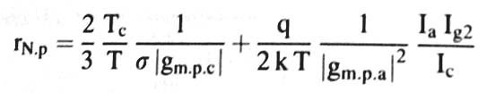
Req= .644 T Ia (1+8Ig2/gm)/(gm Ta Ic)
Original papers:
North, D. O. , Fluctuations in Space Charge Limited Currents in Multi-collectors, RCA Rev., vol 5, pp. 214-260, October, 1940.
Harris, W. A., Space Charge Limited Current Fluctuations in Vacuum Tube Amplifiers and Input Systems, RCA Rev., vol. 5, pp. 505-524, April, 1941; vol. 6, pp. 114-124, July, 1941.
Spangenberg gives this for an equivalent resistor in the grid circuit for a noiseless triode (for a pentode model):
Req= 2.5 Ip (1+8 I2/Gm)/(Gm Is)
on page 310 to 313 in "Vacuum Tubes". I think Is is space charge limited cathode current, but not sure.
Beck "Thermionic Valves" gives on page 293:
Req= .644 T Ia (1+8Ig2/gm)/(gm Ta Ic)
Original papers:
North, D. O. , Fluctuations in Space Charge Limited Currents in Multi-collectors, RCA Rev., vol 5, pp. 214-260, October, 1940.
Harris, W. A., Space Charge Limited Current Fluctuations in Vacuum Tube Amplifiers and Input Systems, RCA Rev., vol. 5, pp. 505-524, April, 1941; vol. 6, pp. 114-124, July, 1941.
The result needs to have the dimensions of resistance. The left-hand term gets this by inverting gm.
The right hand term has current on top and gm^2 on the bottom. Keep one gm to the side as that gives us the resistance we are looking for.
The other gm on the bottom loses its current because of the current on top, leaving us with 'per volt' on the bottom - which becomes volts on top. kT is thermal energy, which divided by charge becomes volts. This cancels the volts on top - so the formula has the correct dimensions as it stands.
Recent measurements of noise in small-signal pentodes
jackinnj,
There is now a reasonable amount of recent data available indicating that, for audio frequencies, the classic formulas for estimating the equivalent noise resistances of valves (tubes) should be taken with a pinch of salt. This reservation is as valid for the pentode formula as the triode formula: the first term of the formula you snipped is a variant of the classic triode estimation formula of rn eq=2.5/gm, while the second term corresponds to the estimated partition noise added by the pentode’s screen grid.
The classic noise analysis focuses on shot noise in valves operating in the zone limited by space-charge, in which the grid controls the output at the anode – in other words, the circumstances in which we generally use’em! The theory underpinning the classic formulas is in Chapter 5 of Aldert van der Ziel’s Noise, Prentice-Hall, New York, 1954. The formulas are consistent with the set of historical experimental data widely cited for noise in triodes at 30Mhz, set out by T. E. Talpey in Table 4.1 on page 175 of his excellent paper ‘Noise in Grid-Control Tubes’, in the collection Noise in Electron Devices edited by Louis Smullin and Hermann Haus and published by John Wiley and Sons, New York, in 1959. The data in Talpey’s table shows that the classic triode noise formula rn eq=2.5/gm holds fairly well at 30Mhz, which is at the top of the HF/bottom of the UHF radio band. The data is cited elsewhere (see for instance page 487 of Gewartowski, J.W., and Watson, H.A., Principles of Electron Tubes, Van Nostrand, New Jersey, 1965 which can be found on Frank's Electron tube Pages) and the findings and formulas were widely known (see augmented formulae and data on pages 937 and 938 of the 4th edition of the Radiotron Designer’s Handbook).
However, authors of the era do not specify experimental measurements of valve output noise at lower frequencies and modern experimenters have measured triode noise at audio frequencies that is higher than the classic models and formulas anticipate. To illustrate, take the results in Table 2 at page 58 of Frank Blöhbaum’s September 2010 article (‘A New Low-Noise Circuit Approach for Pentodes’ in Volume 0 of Jan Didden’s terrific Linear Audio) and calculate rn eq=2.5/gm from the valve data sheets. The formula estimates equivalent noise resistances that are lower than the measured values.
Higher-than-expected noise measurements were considered in Burkhard Vogel’s subsequent article in the September 2012 edition of Linear Audio, in which he developed formula to include 1/f noise. Both Vogel’s and Blöhbaum’s experimental data shows large contributions of 1/f noise, over and above the shot noise that was the basis of the classic triode noise formulas. 1/f noise is not well-understood and, if the late Per Bak’s studies are any indication, a good explanation would put you in contention for a Nobel Prize.
Frank Blöhbaum’s experimental results are particularly interesting in respect of pentodes. For instance, converting his Table 1 of measured equivalent input noise densities to RMS output voltages shows that pentodes are between 3.4dB and 14.0dB noisier than the same valve strapped as a triode. This is consistent with the general dictum on pentode ‘noisiness’ cited by Morgan Jones (see page 94 of Valve Amplifiers, 4th edition, Newnes, 2012), though it is important to reference this result to output noise. Designing to optimise signal-to-noise ratio also requires reference to input noise densities, and Frank’s Table 1 in his article shows that the pentode’s extra 6dB to 14dB of gain levels the playing field: once gain is accounted for, the equivalent input noise voltage densities of pentodes are comparable to those of the same valve strapped as a triode and, in some cases, are lower.
This points to the usefulness of pentodes as devices with low input capacitance capable of achieving a lot of gain in a single stage, while maintaining a signal-to-noise ratio comparable to that which the triode might achieve – assuming of course that the triode could approach the pentode’s gain! This is, of course, the original rationale for designing and manufacturing small-signal pentodes.
Frank’s results also allow the contribution of partition noise to equivalent input noise voltage densities to be estimated. For the small-signal pentodes he tested, partition noise was between 0.5dB and 3.1dB. Applying his BestPentode connection eliminates this and achieves more gain, to the extent that the triodes became markedly inferior performers against the parameters of gain and input noise voltage density. The caveats on this result are (of course) that we want a lot of gain in a single stage, that we have a clean power supply with a low output impedance across the audio band, and that we are comfortable with the pentode’s distortion spectrum, which can include more higher-order harmonics than the equivalent triode.
On that basis, useful applications could be the input stages of microphone pre-amplifiers, or of phono pre-amplifiers, or and all-in-one voltage and driver stage for a power amplifier (I’m building examples of the last two). By contrast, I’m also building a low-gain line stage for which triodes are better suited – configuring small-signal pentodes for low gain looks like a recipe for a poor signal-to-noise ratio!
It still surprises me that many people still estimate triode noise based solely on the shot noise. It surprises just as much that very few people seem to be aware of the extensive investigations of tube noise that were undertakes over 50 years ago, even people like Vogel. Perhaps the best general introduction to all sources of noise in tubes (with references to the original research) can be found in 'Amplifying Devices and Low Pass Amplifier Design' by E.M Cherry and D.E. Hooper. Possibly its expense puts off most people but I recommend you get your local library to get you a copy.
Cheers
Ian
Cheers
Ian
Will follow up on Cherry and Hooper
Thanks for the tip, Ian - I didn’t know of Cherry and Hooper’s book and will go to the library for a copy.
Regards,
Kim
Thanks for the tip, Ian - I didn’t know of Cherry and Hooper’s book and will go to the library for a copy.
Regards,
Kim
FWIW, in "Basic Electronics for Scientists", Brophy distinguishes between Nyquist and Johnson noise. Nyquist noise is thermal and Johnson noise is quantum state shift.
BTW, anyone who thinks BJTs don't have their own set of woes is badly mistaken. Substantial shot noise is associated with the minority carrier injection phenomenon BJTs rely on to operate.
BTW, anyone who thinks BJTs don't have their own set of woes is badly mistaken. Substantial shot noise is associated with the minority carrier injection phenomenon BJTs rely on to operate.
I am suspicious of those results. See my letter on page 7 of the pdf. His reply to me suggests he does not understand space charge smoothing of shot noise, as he appears to claim that there cannot be a mechanism which suppresses shot noise but not partition noise.bondini said:Designing to optimise signal-to-noise ratio also requires reference to input noise densities, and Frank’s Table 1 in his article shows that the pentode’s extra 6dB to 14dB of gain levels the playing field: once gain is accounted for, the equivalent input noise voltage densities of pentodes are comparable to those of the same valve strapped as a triode and, in some cases, are lower.
I am suspicious of those results. See my letter on page 7 of the pdf. His reply to me suggests he does not understand space charge smoothing of shot noise, as he appears to claim that there cannot be a mechanism which suppresses shot noise but not partition noise.
And I am a liitle uncertain as to Vogrel's understanding of the noise sources in tubes. On page 5 of the pdf he says" As far as I know shot-noise only occurs in the frequency range <100Hz"
Cheers
Ian
Dave,
I was fairly sure that I was not alone when Frank’s results triggered my (mechanical) engineer’s reflexes: I reached for my calculator, the library catalogue, and the internet, in about that order.
Step one was to convert Frank’s input voltage densities to output voltages. This confirmed that pentode output noise was, indeed, as much as 14dB higher than the output noise of the same valve strapped as a triode. OK. That hurdle cleared, I calculated partition noise from Frank’s measurements of noise in pentode mode compared to the noise of the same valve in BestPentode mode. As much as 3dB of partition noise for one valve and as little as 0.5dB for another … hmmm … even allowing for variability in the ratio of screen to anode current, there was more to this than met the eye.
More calculations followed to estimate thermal noise contributions from the rest of the circuit - relatively small. More estimates of excess noise from resistors and the MPSA44A - larger than thermal noise but not sufficient to explain the deviation from the classic theory. I may have calculated incorrectly (mechanical engineers can do that) but, since I couldn’t see anything amiss with Frank’s method or equipment (somebody PLEASE give me a Rohde and Schwarz precision audio analyser and I’ll test pentodes ‘til the cows come home!), I decided to re-visit valve noise theory to find out how it was derived and tested.
Step two: hit the books, as most of the references are far older than the internet. The RCA Review has a succession of articles on noise in valves written by D.O. North, W. A. Harris and B. J. Thompson over the period January 1940 to July 1941 under the title ‘Fluctuations in Space-Charge Limited Currents at Moderately High Frequencies’. Harris and North also wrote on ‘Fluctuations Induced in Vacuum-Tube Grids at High Frequencies’ in the Proceedings of the Institute of Radio Engineers in 1941. E. W. Herold reported on ‘An Analysis of the Signal-to-Noise Ratio of Ultra-High-Frequency Receivers’ in the RCA Review of January 1942, and Aldert van der Ziel appeared in print with M. J. O. Strutt on ‘Signal-Noise Ratio at VHF’ in the September 1946 edition of Wireless Engineer.
William J. Stolze (also from RCA) set out the basic results and formulas in the February 1947 edition of Communications in an article on ‘Input Circuit Noise Calculations for F-M and Television Receivers’, much of which subsequently appeared in the Radiotron Designer’s Handbook. William Harris neatly summarised the state of play in a compendium article in the September 1948 edition of the RCA Review, collecting his own works along with North’s fundamental derivation of the space-charge effect on shot noise, re-stating the classic valve noise formulas derived in earlier papers and confirming their utility by comparison with experimental data for triodes and pentodes at radio frequencies.
The common thread in the historical material was the (understandable) attention concentrated on noise at radio frequencies. The experimental data was, with one exception, derived from tests made at 200kHz or more, and normally at more than 10Mhz. The sole publication on low frequency noise was a note from E. J. Harris and P. O. Bishop on ‘Low-Frequency Noise from Thermionic Valves Working under Amplifying Conditions’ in Nature (No. 4103 of June 1948, page 971) in which they lament that:
Harris and Bishop, from the Biophysics Research Unit of University College, London, found that, at frequencies below 1kHz ‘flicker’ or ‘1/f’ noise became measurable above the shot noise and:
My hopes were up, only to have them dashed by Chapter 8 of Aldert van der Zeil’s 1954 book, Noise, in which he recounts the rather inconsistent results obtained when measuring 1/f noise in tubes at low frequencies. On page 230, he concludes that:
Aldert van der Ziel tentatively suggested in his 1959 contribution to the Smullin and Haus collection of papers Noise in Electron Devices that 1/f noise might be cased by fluctuations in the voltage drop across the thin surface layer on the oxide coating of the cathode. This is repeated on page 490 of Gewartowski and Watson’s 1965 book Principles of Electron Tubes … and that’s about it, folks.
What, no model? No coherent theory, no causal mechanism? No consistent set of measurements with a few outliers? In the words of Captain Jack Sparrow:
And it must have really bugged van der Ziel, because step 3 (my internet trawl) turned up a paper he co-authored in 1984 when was at least 73 years of age, ‘Partition 1/f Noise in Vacuum Pentodes’ (Physica C, 124B (1984) pages 299 to 304). The paper is one of a number written in conjunction with his PhD students, reporting on experiments conducted in an effort to confirm that Peter Handel’s 1/f quantum theory applies to electronic noise. Those experiments form much of the basis for van der Ziel’s 1986 book, Noise in Electronic Devices and Circuits, published by Wiley.
Yippee! Are we there yet? Well, no. While Handel’s theory was championed by van der Ziel for electronic noise, its applicability is hotly contested and is currently denied by the broader scientific community. With that caveat, the 1984 paper tested 6AU6 pentodes and reported the interesting result that, for sharp cut-off pentodes, partition noise was not much suppressed by space-charge (on page 304). At this juncture, the engineer in me will accept any empirical crumb that falls from the scientific table ...
The upshot is that, unless there is a relevant body of work written in another language and yet to be uncovered from Philips or Mazda or some other manufacturer, in 2013 we are without an entirely satisfactory model for noise in valves at audio frequencies. We are reduced to testing them type-by-type, valve-by-valve and, for this alone, we owe Frank Blöhbaum a debt of thanks.
For now, I look forward to some more interesting reading (thank you, Ian), and the odd spot of solder-slinging. Pass me that Rohde and Schwarz analyser please, Jocasta darling.
Kim
I was fairly sure that I was not alone when Frank’s results triggered my (mechanical) engineer’s reflexes: I reached for my calculator, the library catalogue, and the internet, in about that order.
Step one was to convert Frank’s input voltage densities to output voltages. This confirmed that pentode output noise was, indeed, as much as 14dB higher than the output noise of the same valve strapped as a triode. OK. That hurdle cleared, I calculated partition noise from Frank’s measurements of noise in pentode mode compared to the noise of the same valve in BestPentode mode. As much as 3dB of partition noise for one valve and as little as 0.5dB for another … hmmm … even allowing for variability in the ratio of screen to anode current, there was more to this than met the eye.
More calculations followed to estimate thermal noise contributions from the rest of the circuit - relatively small. More estimates of excess noise from resistors and the MPSA44A - larger than thermal noise but not sufficient to explain the deviation from the classic theory. I may have calculated incorrectly (mechanical engineers can do that) but, since I couldn’t see anything amiss with Frank’s method or equipment (somebody PLEASE give me a Rohde and Schwarz precision audio analyser and I’ll test pentodes ‘til the cows come home!), I decided to re-visit valve noise theory to find out how it was derived and tested.
Step two: hit the books, as most of the references are far older than the internet. The RCA Review has a succession of articles on noise in valves written by D.O. North, W. A. Harris and B. J. Thompson over the period January 1940 to July 1941 under the title ‘Fluctuations in Space-Charge Limited Currents at Moderately High Frequencies’. Harris and North also wrote on ‘Fluctuations Induced in Vacuum-Tube Grids at High Frequencies’ in the Proceedings of the Institute of Radio Engineers in 1941. E. W. Herold reported on ‘An Analysis of the Signal-to-Noise Ratio of Ultra-High-Frequency Receivers’ in the RCA Review of January 1942, and Aldert van der Ziel appeared in print with M. J. O. Strutt on ‘Signal-Noise Ratio at VHF’ in the September 1946 edition of Wireless Engineer.
William J. Stolze (also from RCA) set out the basic results and formulas in the February 1947 edition of Communications in an article on ‘Input Circuit Noise Calculations for F-M and Television Receivers’, much of which subsequently appeared in the Radiotron Designer’s Handbook. William Harris neatly summarised the state of play in a compendium article in the September 1948 edition of the RCA Review, collecting his own works along with North’s fundamental derivation of the space-charge effect on shot noise, re-stating the classic valve noise formulas derived in earlier papers and confirming their utility by comparison with experimental data for triodes and pentodes at radio frequencies.
The common thread in the historical material was the (understandable) attention concentrated on noise at radio frequencies. The experimental data was, with one exception, derived from tests made at 200kHz or more, and normally at more than 10Mhz. The sole publication on low frequency noise was a note from E. J. Harris and P. O. Bishop on ‘Low-Frequency Noise from Thermionic Valves Working under Amplifying Conditions’ in Nature (No. 4103 of June 1948, page 971) in which they lament that:
Although there is a good deal of information concerning the noise produced by thermionic valves at radio frequencies, there do not appear to have been published data for the low-frequency noise intensity that they produce at under amplifying conditions. It has long been known that the noise intensity increases as the frequency to which the observational system is tuned is diminished.
Harris and Bishop, from the Biophysics Research Unit of University College, London, found that, at frequencies below 1kHz ‘flicker’ or ‘1/f’ noise became measurable above the shot noise and:
if expressed as an equivalent fluctuation EMF at the grid, the low-frequency noise was remarkably constant from valve to valve.
My hopes were up, only to have them dashed by Chapter 8 of Aldert van der Zeil’s 1954 book, Noise, in which he recounts the rather inconsistent results obtained when measuring 1/f noise in tubes at low frequencies. On page 230, he concludes that:
Because flicker effect may vary strongly from tube to tube and from type to type, few suggestions about low-frequency circuits can be given. One should, of course use tubes with low flicker noise: tube types 6AG5, 6CB6, Philips EF40 are recommended; it is in general advisable to select tubes.
[I hope we’ve all bought our stashes of these ...]Aldert van der Ziel tentatively suggested in his 1959 contribution to the Smullin and Haus collection of papers Noise in Electron Devices that 1/f noise might be cased by fluctuations in the voltage drop across the thin surface layer on the oxide coating of the cathode. This is repeated on page 490 of Gewartowski and Watson’s 1965 book Principles of Electron Tubes … and that’s about it, folks.
What, no model? No coherent theory, no causal mechanism? No consistent set of measurements with a few outliers? In the words of Captain Jack Sparrow:
Well, that’s just maddeningly unhelpful.
And it must have really bugged van der Ziel, because step 3 (my internet trawl) turned up a paper he co-authored in 1984 when was at least 73 years of age, ‘Partition 1/f Noise in Vacuum Pentodes’ (Physica C, 124B (1984) pages 299 to 304). The paper is one of a number written in conjunction with his PhD students, reporting on experiments conducted in an effort to confirm that Peter Handel’s 1/f quantum theory applies to electronic noise. Those experiments form much of the basis for van der Ziel’s 1986 book, Noise in Electronic Devices and Circuits, published by Wiley.
Yippee! Are we there yet? Well, no. While Handel’s theory was championed by van der Ziel for electronic noise, its applicability is hotly contested and is currently denied by the broader scientific community. With that caveat, the 1984 paper tested 6AU6 pentodes and reported the interesting result that, for sharp cut-off pentodes, partition noise was not much suppressed by space-charge (on page 304). At this juncture, the engineer in me will accept any empirical crumb that falls from the scientific table ...
The upshot is that, unless there is a relevant body of work written in another language and yet to be uncovered from Philips or Mazda or some other manufacturer, in 2013 we are without an entirely satisfactory model for noise in valves at audio frequencies. We are reduced to testing them type-by-type, valve-by-valve and, for this alone, we owe Frank Blöhbaum a debt of thanks.
For now, I look forward to some more interesting reading (thank you, Ian), and the odd spot of solder-slinging. Pass me that Rohde and Schwarz analyser please, Jocasta darling.
Kim
Kim, I applaud your approach. I was similarly excited to see Vogel's article in Vol 4 of Linear Audio. This gave way to a similar frustration as yours when the upshot was, "You have to test them and they will not be consistent."
Unfortunately, the bottom line is that because the critical parameters (from a QC point of view) are numerous and not well-controlled, and unlike solid state, the reliance isn't just on the fundamental physics of operation but also gross mechanical and chemical variability, we're stuck with very general rules of thumb and... that's pretty much it.
Unfortunately, the bottom line is that because the critical parameters (from a QC point of view) are numerous and not well-controlled, and unlike solid state, the reliance isn't just on the fundamental physics of operation but also gross mechanical and chemical variability, we're stuck with very general rules of thumb and... that's pretty much it.
I thought it was well established theory that partition noise is not suppressed by (cathode) space charge at all; that can only reduce the (shot) noise in the total electron stream but can do nothing about the partition noise as each electron lands randomly on g2 or anode. There may be another space charge around g3 and this could affect partition noise - perhaps that is what the paper was about?bondini said:With that caveat, the 1984 paper tested 6AU6 pentodes and reported the interesting result that, for sharp cut-off pentodes, partition noise was not much suppressed by space-charge (on page 304).
At audio frequencies it may be the case that 1/f noise completely dominates, but that cannot mean that partition noise in pentodes somehow reduces (input-referred) overall noise - as Frank appears to claim. He may be confusing voltage gain (high in pentodes vs. triodes) with transconductance (similar in pentodes and triodes). The best that might be achieved is the 20% (or so) boost in gm from combining g2 and anode currents, not the big improvement he reported.
If partition noise is a major source of 1/f noise then at audio frequencies a pentode should be much noise than a triode, and then his g2 cascode trick will greatly reduce noise. In practice I think it is found that a well-designed pentode has only a little more audio noise than a triode, presumably because 1/f noise from the cathode swamps partition noise (which is mainly white). This implies two things: his measurements were faulty; his solution will not help.
I found that if I ignored/disconnected the plate completely, moving the load resistor to the collector exclusively, the results I got (admittedly limited sample set, a couple of D3a and a 6AU6) were very similar to Frank's. This explicitly configures g2 as the plate and the bipolar as the upper element in a cascode. It would be interesting if someone could see if this holds more generally...
Secondary emission could complicate things, although if that is a noise source I would expect it to get worse at higher frequencies.
The rest is noise?
I sympathise Stuart, though on reflection, my second last paragraph reads bleakly - I was worn down in the telling of the tale ... and I’d forgotten about Jocasta ...
Personally, I have arrived at the view that Frank’s measurements are probably sound - in the absence of a decent noise model derived from a plausible cause, Frank’s results leave me with little confidence in the accepted formulas for valve noise, at least at audio frequencies. Those results also point to a way of using small-signal pentodes (for high gain in a single stage in Frank's BestPentode mode with a good power supply), flying in the face of the formulas, as it were, and opening up the range of glass bottles we can play with. Yes, it’s likely that actual noise performance will be determined valve-by-valve, though I’m hoping that the variability will probably be less for really well-made valves like the D3a and the 7788.
While I’m taking baby steps, I’m putting my (small amounts of) money where my mouth is. Encouraged by Frank and Jan, I am playing with the 6F12P in a one-bottle-per-channel BestPentode phono preamp. I’m also building 6688s in a long-tailed BestPentode pair to drive a pair of 6CZ5s in push pull. Progress is slow (earning a living comes first) but both projects will be up and running by the end of this Southern summer.
If all goes well, and I learn a lot, then 12HG7s EF184s 12HL7s 6BN11s 8077s 7788s and D3as will beckon ... the rest is silence.
Kim
The eefect of 1/f noise in audio was well known over 70 years ago and extensively studied. The main conclusion was that the causes were not understood but they did vary considerably from tube to tube from the same production batch. It was common amongst suppliers of professional audio to select tubes for lowest noise, give them special numbers and fit them to the first stage of their mic preamps..
I have mentioned Cheery and Hooper as a good treatise on all the sources of noise in tubes. There is also an excellent monograph by F.N.H. Robinson called 'Noise in Electrical Circuits' (Oxford University press 1962) that collates all this information in one handy book. He brings out several key point about flicker (1/f) noise.
1. Flicker noise, like shot noise, occurs when the current in a circuit is controlled by a barrier, but whereas shot noise is caused by the random way that electrons mount the barrier, flicker noise is due to variations in the effectiveness of the barrier.
2. The general behaviour of flicker noise is as though the circuit contained a variable resistance. Thus the mean square noise voltage is proportional to the square of the current.
3. Flicker noise in tubes is due to random changes in the emissivity of the cathode. The magnitude varies from tube to tube and during tube life.
4.Its dependence on the square of the current is obscured by space charge effects but Harris found that flicker noise in many small receiving tubes can be represented +_50% by an equivalent input noise resistance of:
Rf = 1 x10^6/f. The integral of this from 1Hz to 1KHz gives an average Rf of 42K.
If you integrate flicker noise over a more normal bandwidth for audio purposes from 10Hz to 1KHz, the average is 4.2K which is equivalent to a noise voltage of about 1.16uV. So it would appear we can expect flicker noise in the average triode to be in the 1uV region +- 50%.
Cheers
Ian
Harris found that flicker noise in many small receiving tubes can be represented +_50% by an equivalent input noise resistance of:
Rf = 1 x10^6/f. The integral of this from 1Hz to 1KHz gives an average Rf of 42K.
Unfortunately, Harris' statement was derived from measurements of only eight valves (1930s/40s types), so is a gross estimation for other types.
In general, shot noise in triodes varies from about
Req = 2.2/gm to 4/gm.
The crossover frequency normally falls between about 10oHz and a few kilohertz (but may be tens of kilohertz in some very poor specimens).
From this data you can sketchthe likely range of input noise spectral density for any triode. Pentodes need to have partition noise added to this, of course.
1uV is a good ballpark figure to keep in your head, though high-gm types can consistently get below 0.5uV.So it would appear we can expect flicker noise in the average triode to be in the 1uV region +- 50%.
1uV is a good ballpark figure to keep in your head, though high-gm types can consistently get below 0.5uV.
This to me seems counter-intuitive. Flicker noise is proportional to current squared and gm increases with current. Using a high gm tube might lead to a lower flicker noise but you don't want to be operating it at high current/ high gm point as this will reduce shot noise but increase flicker noise.
For lowest flicker noise you need low current and for lowest shot noise you need high current. Somewhere between these two extremes there should be an optimum noise operating point.
Cheers
Ian
For lowest flicker noise you need low current and for lowest shot noise you need high current. Somewhere between these two extremes there should be an optimum noise operating point.
Yes that is exactly true, especially for low-gm tubes. However, for for high-gm types the 'optimum' becomes quite broad, so you can be quite relaxed about the exact operating current and still be fairly confident that the total noise will be almost as good as can be hoped for, and almost certainly better than any low-gm type you might otherwuise have used.
(Flicker noise tends to be less troublesome to the ear, too, so reducing shot noise might be a higher concern anyway).
- Home
- Amplifiers
- Tubes / Valves
- Pentode noise