As some of you will know (especially those who hang around the FR forum) I considered just about every cabinet design available for my pair of A10.2s. Then I considered them all again. And again. Paralysis through analysis!
Yesterday I was reading the http://www.diyaudio.com/forums/mark...lectric-300b-bravo.html?highlight=10.2+pensil thread and I said, "Enough is enough! I'm building the Pensil 10.2!"
Stopped by the local HD on the way home and bought a 4x8x3/4" sheet of grade A/B maple veneer-core ply (Columbia MPX Core). Not BB, but the next best type of ply and no vendor in my city stocks 4x8 sheets of BB. Special order only and well over $100 a sheet. Should provide a beautiful finish, too.
Below are some photos of my progress so far. I cut the driver holes and rebates with a Dremel + hole-cutting jig. Not a great idea. It worked, but I burned out the Dremel on the final cut. Either way, I am happy with the results. I basically just used the Dremel + jig to cut the largest hole to the proper rebate depth, then used the same setup to cut all the way through for the driver hole, then used a flat-head screwdriver (couldn't find my chisel) to remove the excess material. It just happened to be exactly 3 layers of ply 🙂
I realized one side-benefit of the separate driver bezel; one can use it to check and recheck the rebate size/depth while the driver sits safely in the box. It is also handy for marking screw-hole locations. I always drill pilot holes and fully screw one of the provided hex-head screws into each pilot hole (and back out again) early in the process. This eliminates the risk of cracking the wood (not much to work with!) and dramatically reduces the risk of slipping and pushing the screwdriver through the cone during installation.
Tonight I will chamfer/round the back-side of the driver cutout, glue the driver bezels in place (thinking LePage Contact Cement will work well) and do a final driver fitting.
If I have time, I will then begin the gluing...
An externally hosted image should be here but it was not working when we last tested it.
An externally hosted image should be here but it was not working when we last tested it.
An externally hosted image should be here but it was not working when we last tested it.
Last edited:
That mirror is a nice reflection of your work.
Not quite sure how to interpret this... 😕
"mirror" + "reflection" = poor attempt at humor.
Good fit on the trim rings.
I've decided to use the compact 10.2 enclosure that Mark uses. His is a bit modified from the actual plans, but I won't be using them in a true full-range implementation, more like a FAST.
Good fit on the trim rings.
I've decided to use the compact 10.2 enclosure that Mark uses. His is a bit modified from the actual plans, but I won't be using them in a true full-range implementation, more like a FAST.
"mirror" + "reflection" = poor attempt at humor.
Good fit on the trim rings.
I've decided to use the compact 10.2 enclosure that Mark uses. His is a bit modified from the actual plans, but I won't be using them in a true full-range implementation, more like a FAST.
Ah, I see. 🙂 I sort of thought that, but there's also a terrible-looking door in the reflection (ex-owner's dog must have been left in the basement a lot).
I have had temptations towards FAST-like setups, however I resist for several reasons:
1) I don't think I have yet explored enough pure full range setups to pass judgement on them just yet.
2) FAST introduces much of the complexities that come with any multi-way systems. Perhaps even more, like active crossovers, DSP, multi-amping, etc. I like simple; one integrated amp and a pair of speakers.
3) I have listened to many, many small-speaker + sub variations. My conclusion is that they are much easier to get wrong, than right. Plus, there are far more ugly subs out there than beautiful ones.
4) Related to point 1 above - By the time I have fully explored true full-range systems, Mark and others will have made more advancements in driver technology which will further reduce the need for more than 2 drivers in a system. 🙂
As some of you will know (especially those who hang around the FR forum) I considered just about every cabinet design available for my pair of A10.2s. Then I considered them all again. And again. Paralysis through analysis!
I realized one side-benefit of the separate driver bezel; one can use it to check and recheck the rebate size/depth while the driver sits safely in the box. It is also handy for marking screw-hole locations.
I always drill pilot holes and fully screw one of the provided hex-head screws into each pilot hole (and back out again) early in the process. This eliminates the risk of cracking the wood (not much to work with!) and dramatically reduces the risk of slipping and pushing the screwdriver through the cone during installation.
Hi Cogitech,
Glad you've decided to make Pensil 10's. Glad you're using the frame covers. I spent a great deal of research time/effort over the years developing the high-pressure injection method to make it possible to accurately produce these frames/covers. The investment to date has cost us US$70.000, thats allot for a small company like ours. The production system allowed me to produce a single piece unit using 3 mixes of polymer. The frames are very stable with a very effective resonant damping characteristics. Try flicking a steel or cast frame, most ring like a bell. So the dedicated frame is an important part of the effective operation of a Markaudio driver. Technical gains when fitting/using the cover are:
1 - Bonding the cover to the frame increased frame stiffness and twisting resistance by 10%. Frame damping effectiveness is also further improved.
2 - (as you've found), the cover also acts as a practical aid for checking the rebate fit.
3 - Using the cover further encourages project builders to keep the driver mounting thickness in the front baffle to a minimum. While this can be a wood-working challenge, it's Critical to keep this side wall thickness to a minimum, thus avoiding the risk of internal reflections returning to strike the rear of the cone.
Glad you're making pilot holes. When time permits me to make boxes (very rare alas), I always recess the drivers and make pilot holes. Always best to employ this method.
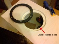
While you have the opportunity, please check the flatness of your rebates (see pic). Make sure they are accurate. If there is some minor variation, use a little silicone or rubberised sealer (the sort used on windows, bathrooms etc) and GENTLY screw the driver into position taking care to "nip up" the screws. They don't need to be very tight, just enough to secure the driver. Don't use a power-screw driver to do this operation. Use a hand tool so you can "feel" the bite of each screw.
Use a flat steel ruler and eyeball the flatness of the frame fit into to baffle. Adjust individual screw tension to achieve frame installation flatness.
Apologies should you already know all of this, its good to remind/help newer members reading this thread. So I much welcome more posts from you.
Cheers
Mark.
Attachments
Last edited:
"mirror" + "reflection" = poor attempt at humor.
Good fit on the trim rings.
I've decided to use the compact 10.2 enclosure that Mark uses. His is a bit modified from the actual plans, but I won't be using them in a true full-range implementation, more like a FAST.
Hi Sil,
I'd advise against adding FAST (woofer assist) to 10.2's in Pensil. If you're a head twirling acid house, rock un roll fan intent of blowing out ear-drums, consider FAST, otherwise there should be no need to assist the Pensil's LF output. Adjust the Pensil's internal damping volume to suit your room environment. If your environment is heavily damped, then consider adding FAST, but extra LF is rarely needed on Pensils.
Should you (in the end) decide to go the FAST rout, think very carefully about your choice of woof. Its by no means all sweetness and musical light when it comes to finding a descent LF emitter capable a generating "actual music" in the LF range. Take a look at post 120 on this thread:
http://www.diyaudio.com/forums/markaudio/224477-future-woofer-production-13.html
Thanks
Mark.
Last edited:
Mark,
I just think it is incredible to be receiving direct support and advice from the guy who actually designed the drivers I love so much! This is a unique and wonderful experience, which I appreciate very much. You have earned yet another loyal customer!
What makes it even better is that the designers of all these wonderful cabinets are here in the forum, too. Incredible!
Regarding the info you offered on the frame/cover design process; very interesting! Thanks for sharing that info with me. I am one who loves to know as much as I can about the way things are designed, so as to best take advantage of their features.
Regarding your advice; much of it I have learned from some of your knowledgeable disciples around here but, like you said, it is never a bad thing to be reminded. I suspected that large inconsistencies in the flatness of the rebates would create gaps (air leaks) so I had though of smoothing some carpenter's glue on there and letting it level itself and then cure, for a plastic-like smooth finish for the rubber gasket to seal to. I was thinking I would install the 6 screws before applying the glue, to avoid the obvious "oops". When you recommended the caulking, did you intend for me to let it cure first? Otherwise, the driver will become bonded to the baffle.
Below I have posted some more photos of my progress. I got the cabinets basically built (minus the back panels) last night. I even did a driver fitting test and then brought one speaker up to the living room for a (low volume!) test. No lining or stuffing, just the driver in the box with rubber bands and clamps holding the back panel on. The sound was quite nice already! Very exciting!
Some of you will immediately notice that I deviated from the standard Pensil 10.2 build. I did this because I prefer to have the front baffle "in front" of the two side panels rather than inset between them. I think it gives a cleaner look to the front of the speaker (no plywood edges running down each side) and I think it also increases the rigidity of the front baffle. This, however, results in the bottom slot looking rather ugly. I will address this by adding a grill to that slot.
Regarding bracing; I would have liked to go full out and do end-to-end holey braces, but 2 of my goals for this project (1 sheet of plywood and quick turnaround) limited my bracing options. I did have some scraps left over and I just used my intuition to install some bracing in the mid-section, concentration on the two large side panels and the area immediately near the driver.
Now, the question of stuffing/lining: I will be doing this tonight, so I would like any advice that people have to offer. Scott's plans prescribe 1.6 pounds of polyfil. Is that all? No lining at all? Just distribute the polyfil evenly?
I know I should trust Scott on that, and stuffing will need to be adjusted to taste, but I am temped to take an entirely different approach. I am thinking 1" fiberglass insulation on the top, back, and one entire side, plus strips of it on the edges of the braces nearest the driver. Then polyfil from just below the driver to the bottom of the braces.
Is this a terrible idea? I know there is only one way to find out, but if it would be a waste of time, please let me know.
Reflections eliminated:
On the bench:
Gluing the braces in:
The braces:
The test:
I just think it is incredible to be receiving direct support and advice from the guy who actually designed the drivers I love so much! This is a unique and wonderful experience, which I appreciate very much. You have earned yet another loyal customer!
What makes it even better is that the designers of all these wonderful cabinets are here in the forum, too. Incredible!
Regarding the info you offered on the frame/cover design process; very interesting! Thanks for sharing that info with me. I am one who loves to know as much as I can about the way things are designed, so as to best take advantage of their features.
Regarding your advice; much of it I have learned from some of your knowledgeable disciples around here but, like you said, it is never a bad thing to be reminded. I suspected that large inconsistencies in the flatness of the rebates would create gaps (air leaks) so I had though of smoothing some carpenter's glue on there and letting it level itself and then cure, for a plastic-like smooth finish for the rubber gasket to seal to. I was thinking I would install the 6 screws before applying the glue, to avoid the obvious "oops". When you recommended the caulking, did you intend for me to let it cure first? Otherwise, the driver will become bonded to the baffle.
Below I have posted some more photos of my progress. I got the cabinets basically built (minus the back panels) last night. I even did a driver fitting test and then brought one speaker up to the living room for a (low volume!) test. No lining or stuffing, just the driver in the box with rubber bands and clamps holding the back panel on. The sound was quite nice already! Very exciting!
Some of you will immediately notice that I deviated from the standard Pensil 10.2 build. I did this because I prefer to have the front baffle "in front" of the two side panels rather than inset between them. I think it gives a cleaner look to the front of the speaker (no plywood edges running down each side) and I think it also increases the rigidity of the front baffle. This, however, results in the bottom slot looking rather ugly. I will address this by adding a grill to that slot.
Regarding bracing; I would have liked to go full out and do end-to-end holey braces, but 2 of my goals for this project (1 sheet of plywood and quick turnaround) limited my bracing options. I did have some scraps left over and I just used my intuition to install some bracing in the mid-section, concentration on the two large side panels and the area immediately near the driver.
Now, the question of stuffing/lining: I will be doing this tonight, so I would like any advice that people have to offer. Scott's plans prescribe 1.6 pounds of polyfil. Is that all? No lining at all? Just distribute the polyfil evenly?
I know I should trust Scott on that, and stuffing will need to be adjusted to taste, but I am temped to take an entirely different approach. I am thinking 1" fiberglass insulation on the top, back, and one entire side, plus strips of it on the edges of the braces nearest the driver. Then polyfil from just below the driver to the bottom of the braces.
Is this a terrible idea? I know there is only one way to find out, but if it would be a waste of time, please let me know.
Reflections eliminated:
An externally hosted image should be here but it was not working when we last tested it.
On the bench:
An externally hosted image should be here but it was not working when we last tested it.
Gluing the braces in:
An externally hosted image should be here but it was not working when we last tested it.
The braces:
An externally hosted image should be here but it was not working when we last tested it.
The test:
An externally hosted image should be here but it was not working when we last tested it.
Last edited:
Cogitech,
I would suspect that your implemtation might have a slight effect on port tuning - let the experts chime in. 🙂
I would suspect that your implemtation might have a slight effect on port tuning - let the experts chime in. 🙂
\
On the bench:
An externally hosted image should be here but it was not working when we last tested it.
With this construction you have a vent that is 0mm deep instead of the specified 18-20mm.
dave
And which (with respect) looks rather 'awkward', at least to my eyes. To each their own of course, & long may it remain so.
It's difficult to gauge the effects of the change in practice, since the lip above & the floor boundary will have some impact, but I'd anticipate Fb being raised by about 5Hz with a little more gain peaking. Theoretically this could be ameliorated by increasing the stuffing density, since I made the pensils adjustable via the damping, although going to high levels is not without its own issues. With that said, the quantities used are actually relatively modest compared to, say, some of the sealed box designs you often encounter, or some TL boxes from a few years back, so YMMV on that score. Just keep the density around / near the driver fairly modest if you do increase the overall packing to reduce the chances of it mass-loading the cone sufficiently to distort the diaphragm under dynamic load conditions. It's unlikely to damage the driver but the midband / HF will probably sound rubbish since it won't be able to resonate as designed.
It's difficult to gauge the effects of the change in practice, since the lip above & the floor boundary will have some impact, but I'd anticipate Fb being raised by about 5Hz with a little more gain peaking. Theoretically this could be ameliorated by increasing the stuffing density, since I made the pensils adjustable via the damping, although going to high levels is not without its own issues. With that said, the quantities used are actually relatively modest compared to, say, some of the sealed box designs you often encounter, or some TL boxes from a few years back, so YMMV on that score. Just keep the density around / near the driver fairly modest if you do increase the overall packing to reduce the chances of it mass-loading the cone sufficiently to distort the diaphragm under dynamic load conditions. It's unlikely to damage the driver but the midband / HF will probably sound rubbish since it won't be able to resonate as designed.
Last edited:
With this construction you have a vent that is 0mm deep instead of the specified 18-20mm.
dave
Interesting. It did not occur to me that it is a "vent" in the traditional sense.
I had assumed it is simply a termination point, and that the height and width were the critical dimensions, whereas the "depth" was a simple function of the material used.
An externally hosted image should be here but it was not working when we last tested it.
Last edited:
And which (with respect) looks rather 'awkward', at least to my eyes. To each their own of course, & long may it remain so.
It's difficult to gauge the effects of the change in practice, since the lip above & the floor boundary will have some impact, but I'd anticipate Fb being raised by about 5Hz with a little more gain peaking. Theoretically this could be ameliorated by increasing the stuffing density, since I made the pensils adjustable via the damping, although going to high levels is not without its own issues. With that said, the quantities used are actually relatively modest compared to, say, some of the sealed box designs you often encounter, or some TL boxes from a few years back, so YMMV on that score. Just keep the density around / near the driver fairly modest if you do increase the overall packing to reduce the chances of it mass-loading the cone sufficiently to distort the diaphragm under dynamic load conditions. It's unlikely to damage the driver but the midband / HF will probably sound rubbish since it won't be able to resonate as designed.
Awkward looking, yes, however I did explain earlier my plan to add a grill there.
Thanks for your perspective on the possible auditory effects. Having you guys around here is amazing, as I said earlier.
Another quite simple option would be to include the missing 3 sides of the "port" in the grill frame that I plan to make. This may be difficult to imagine, but it is actually quite a simple plan. Necessity is the mother of invention. I'll figure it out, and post my solution here later.
Thanks to all who have highlighted this issue. I really did think a terminus was 2-dimensional, and that the 3rd dimension (depth) was simply determined by the material itself.
Last edited:
Mark,
I just think it is incredible to be receiving direct support and advice from the guy who actually designed the drivers I love so much! This is a unique and wonderful experience, which I appreciate very much. You have earned yet another loyal customer! What makes it even better is that the designers of all these wonderful cabinets are here in the forum, too. Incredible!
Regarding your advice; much of it I have learned from some of your knowledgeable disciples around here but, like you said, it is never a bad thing to be reminded. I suspected that large inconsistencies in the flatness of the rebates would create gaps (air leaks) so I had though of smoothing some carpenter's glue on there and letting it level itself and then cure, for a plastic-like smooth finish for the rubber gasket to seal to. I was thinking I would install the 6 screws before applying the glue, to avoid the obvious "oops". When you recommended the caulking, did you intend for me to let it cure first? Otherwise, the driver will become bonded to the baffle.
Hi C, (guys)
Glad to be of assistance. There's allot of goodwill on this section of Diyaudio, glad its developed over recent years as its helped many builders enjoy the hobby. I'm now at week 4+ out from my major surgery, gradually improving so feeling more energised to assist folks as best I can.
Re flattening the rebate with carpenter's glue sounds good, worth testing on a old piece of wood/ply prior to working it into the rebates. In the past I've used flexible bathroom sealants that don't set hard, just a thin beed run in the middle of the rebate, has worked well for me. Keeping the screw holes clear of glue is a good practical tip. I always run the screws in and out a couple times to make the threads prior to installing the driver.
Hope you keep posting as it helps other project builders, especially the newer guys.
Cheers
Mark.
I am really glad that you are feeling better, Mark!
Indeed I will keep posting so others can learn from my mistakes. Hopefully I can offer solutions to my mistakes to show I am not a complete imbecile as well. 🙂
Indeed I will keep posting so others can learn from my mistakes. Hopefully I can offer solutions to my mistakes to show I am not a complete imbecile as well. 🙂
First time I ever noticed the 13-14khz content over on left back stage on the song AJA.
Resisting urge to turn up the volume is killing me!
Resisting urge to turn up the volume is killing me!
Quick question:
Can I expect the break-in period, and corresponding performance improvement, of the Alpair 10.2 to equal that which I experienced with the EL70 drivers?
Can I expect the break-in period, and corresponding performance improvement, of the Alpair 10.2 to equal that which I experienced with the EL70 drivers?
First time I ever noticed the 13-14khz content over on left back stage on the song AJA.
Well I can remember "not" hearing it. Fortunately, I can still hear it if it's there.😉
jeff
- Status
- Not open for further replies.
- Home
- More Vendors...
- Planet 10 hifi
- Pensil 10.2 Build (Yet Another)