Special the pre !!! Awesome!!! I am an hfe_animal and i have found couples from 800 bc's! Dead silence!!!

Posting here to get some help.
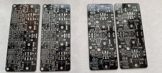
I seem have to run into a small issue. I just swapped the chassis of the amp and 1 of the channels is not giving out any sound.
I reflowed the entire board assuming there might have been some dry solder and re did the complete biasing as per the build guide.
The VAS is set to 600mv and the output bias is set of 13mv. The amp is nice and warm and the offset is stable too.
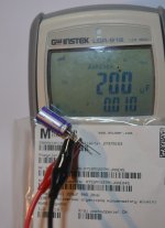
Connected the signal and tried again but no luck. I am confused now 😞.. the DMM on the left showing the offset and on the right Bias.

I seem have to run into a small issue. I just swapped the chassis of the amp and 1 of the channels is not giving out any sound.
I reflowed the entire board assuming there might have been some dry solder and re did the complete biasing as per the build guide.
The VAS is set to 600mv and the output bias is set of 13mv. The amp is nice and warm and the offset is stable too.
Connected the signal and tried again but no luck. I am confused now 😞.. the DMM on the left showing the offset and on the right Bias.
I hope the modules are running well following our phone conversation.Posting here to get some help.
I seem have to run into a small issue. I just swapped the chassis of the amp and 1 of the channels is not giving out any sound.
I reflowed the entire board assuming there might have been some dry solder and re did the complete biasing as per the build guide.
The VAS is set to 600mv and the output bias is set of 13mv. The amp is nice and warm and the offset is stable too.
Connected the signal and tried again but no luck. I am confused now 😞.. the DMM on the left showing the offset and on the right Bias. View attachment 1198954
Hi Jorgovanko.
Good idea. Will add this to the next revision of the amp.
Another couple changes will also be added, namely C15 and C16 change to 100pF from 220pF, and R19 amd R20 change to 1K from 470R. The first mod improves the slew a bit and the second one further stabilizes the VAS-O/P loop.
A smaller cap for the diamond drivers lowered the capacitive load for the predrivers, so speed improves a bit.
The default 470R for O/P inclusive feedback resistor did not make it unstable but with this value the amp is closer to the threshold than I like. 1K puts the amp far from it and is sufficiently low that the feedback effectively works the way it should.
Existing V5 builders can install both mods without much hassle. Remove the module from heatsink, remove the four small components, replace with the new ones, re-install module to heatsink and done. DC bias and offset remain unaffected so no need to re-bias.
For anyone interested, a few PCBs are left from last batch. As per the reports I am getting from those who built and listened to V5, you're in for a treat.
PM me to get your boards.
PM me to get your boards.
Hi shaan,
Holidays or just super busy like most of us ?. Let me know if any boards left for purchase. See PM.
Happy holidays and best to you and family.
MM
Holidays or just super busy like most of us ?. Let me know if any boards left for purchase. See PM.
Happy holidays and best to you and family.
MM
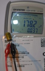
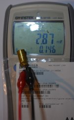
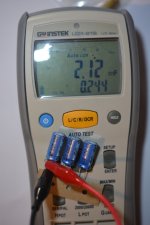
hi, what about C3/4 - those also can have lower values? my 2.2mF caps measures 1.8mF, so i'm bit puzzled 😛The 2200uF (C17) between the OPS drivers' bases is oversized. It could be as small as 10uF and the amp would still work fine. But I left it there because I thought the board looked cool with it.
if those parts are important then i'll order some more and try to match to avaited value.
also... 🙂
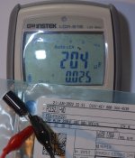
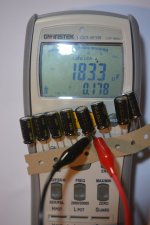
-my 220uF caps [C19...26] measures closer to 180uF, isn't it to low? i have some leftover caps from Wolverine (~250-260uF range) so i can use those if it won't do harm to v5 performance;
-if one would like to use this board with +-28V rails [source: smps; low power system or active channels] - what changes should be made to components values (any??);
-my DAC outputs ~2.2VRMS at 0dbFS. is there a way to lower input sensitiwity that with +-28V rails PeeCeeBee v5 won't clip?
cap measurments made with LCR916 @100Hz;
hi, what about C3/4 - those also can have lower values? my 2.2mF caps measures 1.8mF, so i'm bit puzzled 😛
if those parts are important then i'll order some more and try to match to avaited value.
1800uF is fine. There will not be any LF attenuation in the audible zone.
also... 🙂
-my 220uF caps [C19...26] measures closer to 180uF, isn't it to low? i have some leftover caps from Wolverine (~250-260uF range) so i can use those if it won't do harm to v5 performance;
Even 100uF will work, but I feel a bit concerned about the quality of the caps that as you say, apparently measure close to their -20% range. But then again the lower measured values seem consistent in both cases of large value and small value caps. Maybe it has something to do with the meter. I think all your capacitors are just fine.
-if one would like to use this board with +-28V rails [source: smps; low power system or active channels] - what changes should be made to components values (any??);
None. 🙂
-my DAC outputs ~2.2VRMS at 0dbFS. is there a way to lower input sensitiwity that with +-28V rails PeeCeeBee v5 won't clip?
Use a 10uF 63V input cap + 50% divider by a 10Kohm resistor in series. So it's Capacitor -> 10Kohm -> V5. If your source has no DC at output then omit the 10uF.
Bests.
i think my multimeter doesn't like NICHICON caps 🙂 2.2mF caps shouldn't be older than 3-4years (at most)but I feel a bit concerned about the quality of the caps that as you say, apparently measure close to their -20% range. But then again the lower measured values seem consistent in both cases of large value and small value caps. Maybe it has something to do with the meter. I think all your capacitors are just fine.
for some capacitors my multimeter had such a big difference between measured and specified capacity that i sent it for service/calibration. but it was returned to me with info that multimeter is OK / within specified tolerance --> capacitors were outside the tolerance.
thanks for help / response 🙂 i'll try to finish my boards in next two weeks
Attachments


Hi shaan,
You never sent me any shipping information for the 2 V5 boards I purchased from you on 2023-12-27 Was there a problem.
MM
You never sent me any shipping information for the 2 V5 boards I purchased from you on 2023-12-27 Was there a problem.
MM
Thanks shaan,
Is it OK to use 1/2W resistors (ie:enough room for them). I have most values in my inventory already. Have any other builders used 1/2W resistors rather than 1/4W, without running into lack of space ?
Regards,
MM
Is it OK to use 1/2W resistors (ie:enough room for them). I have most values in my inventory already. Have any other builders used 1/2W resistors rather than 1/4W, without running into lack of space ?
Regards,
MM
- Home
- Group Buys
- PEECEEBEE V5 GB