Hi,
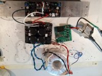
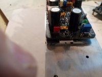
Quick question: With no power switched on. When checking for continuity between the amp output and the heatsink is the PSU connected to the amp module in any way, including the ground wire for the heatsink ?
Thanks,
MM
Quick question: With no power switched on. When checking for continuity between the amp output and the heatsink is the PSU connected to the amp module in any way, including the ground wire for the heatsink ?
Thanks,
MM
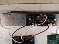
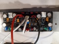
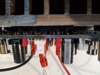
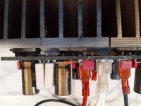
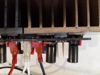
The reason for the question in post#1823 is that with just the amp board mounted on the heatsink (no connection to the psu) and the DMM with COM the black probe attached to heatsink fin and red probe on the amp output. With the DMM in continuity mode I read an OL on the DMM. All the legs on the Mfets are reading OL also.
Earlier comments from shaan indicate that this is correct and one can proceed with further testing. Is this correct?
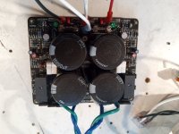
If I connect the psu to the amp board, heatsink to psu gnd, sgnd and pgnd to psu gnd, with no power applied, then the DMM reads resistance from the output and from the Mfets legs. Is this normal operation also ?
Thanks for the help,
MM
I think connecting the heatsink to PSU ground is messing up your resistance measurements.
That said it sounds like without that connection your amp boards are measuring correctly.
As long as you have tested your PSU separately and it performs as you expected, you should be good to power up.
Use a variac or DBT just to be sure on that first switch on. Good luck, getting close.
That said it sounds like without that connection your amp boards are measuring correctly.
As long as you have tested your PSU separately and it performs as you expected, you should be good to power up.
Use a variac or DBT just to be sure on that first switch on. Good luck, getting close.
