Dear Shaan,Important Update:
Hello everyone.
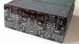
This is the very last batch of PeeCeeBee V4H Rev2 PCBs that are still available to order. After this batch is exhausted no more V4H boards will be printed. A clearance discount of USD5 is added, so the boards are available at USD15 instead of 20.
The main reason for this decision is that sourcing genuine Lateral MOSFETs have become a problem for me. So members who still have access to the MOSFETs may want to consider buying the boards. These will come with the SMD gate-source diodes pre-installed as usual.
Happy Winter!
Please spare me 1 pair of V4H Board, (2Pcs.) my email: odie1427@gmail.com. Hope to hear from you. Thanks
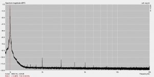
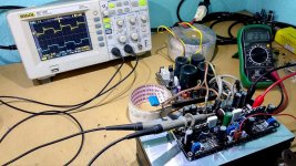
Today I powered one of the V5 channels and played some music. After listening to some tracks for an hour I felt like running to my PC and firing some test tones at the amp. So I did that, and this is what I am getting with 20mA total output bias (10mA per output transistor) and 20Watt into 5ohm test load (first attachment). The second harmonic is negative-phase type (which IME helps to a great deal in long listening sessions without fatigue).
How does it sound? Better than I expected. Well, took it's sweet time...
Full test results will be generated in a few days. I will share rest of the story in a new thread.
Stay tuned! ^^
How does it sound? Better than I expected. Well, took it's sweet time...
Full test results will be generated in a few days. I will share rest of the story in a new thread.
Stay tuned! ^^
Attachments


Good day everyone!
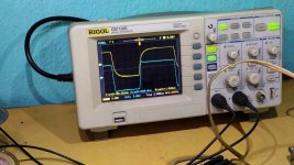
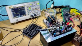
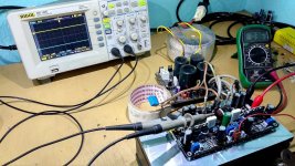
Today I ran some further tests on the V5 amp prototypes. Mainly a capacitive load stability test with the standard 2uF || 10R network, and a basic slew-rate test into my 5R resistive load with 20VPP output. Test signals are fast-rise squarewaves, 5KHz for capacitive load test, and 50KHz for the basic slew-rate test, taken from my old CD40106 based generator. Both the input RF lowpass filter capacitor and output zobel network are present. In all cases the blue trace shows output signal before the onboard 1.5uH+10R network and the yellow trace shows it afterwards, around the capacitive load.
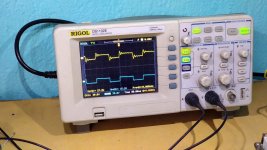
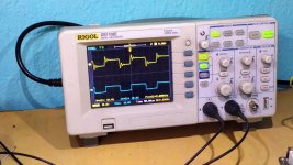
First picture shows the capacitive load test setup. Second picture - 2VPP output. Third picture - 10VPP output. Fourth picture - 15VPP output. The typical damped oscillation at the wave-top and wave-bottom around the capacitive load is present in all cases (yellow trace), whereas the squarewave shape is intact at the output node before the LR network (blue trace), indicating very good stability into reactive load.
Fifth picture shows the basic slew rate test setup. The blue trace indicates a slew rate of 32V/uS, but only at a 10%-90% output range of 16V, and with input lowpass cap installed (sixth picture). I expect (and simulated) a slew-rate of >80V/uS at maximum output levels without the input lowpass filter capacitor. I will publish the final results in the upcoming V5 thread.
The yellow trace shows the squarewave significantly slewed and rounded. This is the effect of the LR network which prevents extremely fast transients to get outside the the amp's internal negative feedback loop and lowers the possibility of oscillation due to HF/RF positive feedback from the output back to the input via external/atmospheric means. I have been listening to the amp for quite some time now. Despite the strong slewing of the squarewave as can be seen in the yellow trace, the treble in the highest frequencies sounds crystal clear and thoroughly enjoyable.
Stay tuned. ^^
Today I ran some further tests on the V5 amp prototypes. Mainly a capacitive load stability test with the standard 2uF || 10R network, and a basic slew-rate test into my 5R resistive load with 20VPP output. Test signals are fast-rise squarewaves, 5KHz for capacitive load test, and 50KHz for the basic slew-rate test, taken from my old CD40106 based generator. Both the input RF lowpass filter capacitor and output zobel network are present. In all cases the blue trace shows output signal before the onboard 1.5uH+10R network and the yellow trace shows it afterwards, around the capacitive load.
First picture shows the capacitive load test setup. Second picture - 2VPP output. Third picture - 10VPP output. Fourth picture - 15VPP output. The typical damped oscillation at the wave-top and wave-bottom around the capacitive load is present in all cases (yellow trace), whereas the squarewave shape is intact at the output node before the LR network (blue trace), indicating very good stability into reactive load.
Fifth picture shows the basic slew rate test setup. The blue trace indicates a slew rate of 32V/uS, but only at a 10%-90% output range of 16V, and with input lowpass cap installed (sixth picture). I expect (and simulated) a slew-rate of >80V/uS at maximum output levels without the input lowpass filter capacitor. I will publish the final results in the upcoming V5 thread.
The yellow trace shows the squarewave significantly slewed and rounded. This is the effect of the LR network which prevents extremely fast transients to get outside the the amp's internal negative feedback loop and lowers the possibility of oscillation due to HF/RF positive feedback from the output back to the input via external/atmospheric means. I have been listening to the amp for quite some time now. Despite the strong slewing of the squarewave as can be seen in the yellow trace, the treble in the highest frequencies sounds crystal clear and thoroughly enjoyable.
Stay tuned. ^^
Attachments
-
 IMG_20230208_153229.jpg732.8 KB · Views: 164
 -
 IMG_20230208_153148.jpg803.1 KB · Views: 169
 -
 IMG_20230208_151552.jpg646.9 KB · Views: 148
 -
 IMG_20230208_151423.jpg717.2 KB · Views: 137
 -
 IMG_20230208_151901.jpg633.4 KB · Views: 149
 -
 IMG_20230208_151142.jpg757.1 KB · Views: 153
 -
 IMG_20230208_151219.jpg748.3 KB · Views: 143
Last edited:
As I see in my phone and browser, the pictures rearranged themselves in a way that does not relate to their indications in the post text.
I have reported this issue to the mods. Until this is solved here is the corrected indication:
First picture mentioned is now in sixth position.
Second is now in fifth.
Third is now in fourth.
Fourth is now in third.
Fifth is now in first.
Hope this helps.
I have reported this issue to the mods. Until this is solved here is the corrected indication:
First picture mentioned is now in sixth position.
Second is now in fifth.
Third is now in fourth.
Fourth is now in third.
Fifth is now in first.
Hope this helps.
Can you post a schematic please? Even without parts values is fine. And which OPS power transistors are you using?Good day everyone!
Today I ran some further tests on the V5 amp prototypes. Mainly a capacitive load stability test with the standard 2uF || 10R network, and a basic slew-rate test into my 5R resistive load with 20VPP output. Test signals are fast-rise squarewaves, 5KHz for capacitive load test, and 50KHz for the basic slew-rate test, taken from my old CD40106 based generator. Both the input RF lowpass filter capacitor and output zobel network are present. In all cases the blue trace shows output signal before the onboard 1.5uH+10R network and the yellow trace shows it afterwards, around the capacitive load.
I'm so happy to be at the head of the queue for this one. 😀
Can you post a schematic please? Even without parts values is fine. And which OPS power transistors are you using?
I'm so happy to be at the head of the queue for this one. 😀
I know. So I shared a little more than just a little more. 🙂Tcpip is right, you have to share a little more with us Shaan!
PeeCeeBee V5 GB
Update:
V4H final batch boards are going out of stock soon. Have about 20 of them left.
To clear them cost has now been lowered again to 10USD only per PCB. So 20USD for a stereo set. As usual they will come with the SMD diodes pre-installed.
Interested members feel free to PM me.
V4H final batch boards are going out of stock soon. Have about 20 of them left.
To clear them cost has now been lowered again to 10USD only per PCB. So 20USD for a stereo set. As usual they will come with the SMD diodes pre-installed.
Interested members feel free to PM me.
Attachments
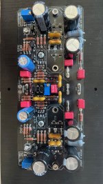
Hi, can you please help me? I feel helpless with my V4H.
It is connected as the manual says. Between PSU (measuring 48-0-48) are two 1R resistors. There is a very big voltage drop after the resistors and opposite polarity on:
Negative imput terminal -3V
Positive imput terminal -0,5V
Output -1,7V
On the pins of D5 is also reversed polarity -1,2 V
I made two boards with the same result, I had to switch a component. I feel like I checked everything 🙁 I can not find the problem.
Can you please help me with a tip where to look?
Thank you very much!
Attachments
first question - without the amp connected is your power supply putting out +/- Vdc, is it the +/-48V you mention above? Generally you write AC as 48-0-48 and DC as +/-48V to help clarify my question and get a good response from you.
If the power supply is working and the only thing you added were resistors? You should check that they are actually measuring 1-ohm, can't tell by your picture if they are 1-ohm, but verify with a DMM.
It would also help to have more than a single picture, like both sides of the power supply and two angles of your amp board.
Lastly - make sure you mount both output transistors to the heatsink, even if a short time you can heat up and damage them with this kind of voltage.
Edit - you mention D5, if D5 and D6 are not lighting up, there won't be a good current source and cause stability issues.
Hi bullittstand,
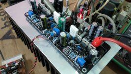
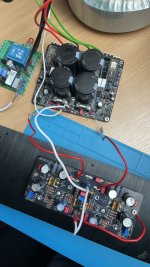
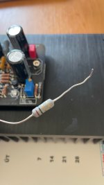
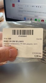
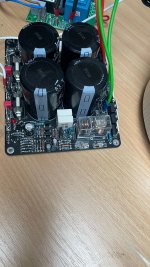
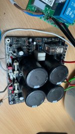
thank you for you answer. I measured the power supply once again to write you accurate voltage and it is +/- 54V. My DDM can not measure small resistor values, but I am uploading here better pictures. They are 1R 5W resistors, which I put between PSU and the amp board.
Today I connected the amp board to my lab power supply set to 45V and both the LEDs lit up. Do you think the problem could be (as someone mentioned in this thread in the past) 1N4148 diodes with a rail voltage above 50V?
Attachments
The 1N4148 should not be your problem, I am running my amp boards at +/-65Vdc without issue - but I'm not sure.
Can you restate the problem? If you boards work on your lab power supply (+/-45V) and your Power Supply is working giving you +/-54V, then you have one of two issues.
1. the amp boards are connected incorrectly to the power supply board (your wiring in the photo seems ok - IMO wire from GND to Output not needed)
2. the power supply board has a problem (i.e. voltage ok with DMM and no load, but problem exists when you connect the amp to it, can't provide current)
Additionally - check your soldering - on Q6 there is one leg that doesn't appear fully soldered to the board. While your at it, grab a magnifier and check all solders on the amp and psu, might be your current leak that's causing you an issue.
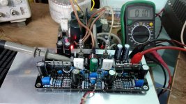
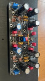
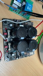
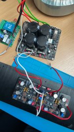
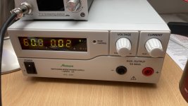
My power supply (Manson HCS-3204-000G) gives me 0 - 60V. I connected plus (PS) to plus (amp), minus to minus and ground from amp to a power socket GND. Today I tried it with 60V, which is +/- 30V referred to GND. Both LED were lit and when trying to bias VAS at VR1, I could see changes in voltage at R25. Weird is, that the board is not taking any current as is seen on the picture (just 0,02 A).
I checked all the solder joints and some of them resoldered.
I checked all the resistors again for the right values and to check if they are not damaged. All of them are ok.
I checked the transistors and they are also ok, so are the diodes.
The position of the components should be ok (I dont see any displacement).
There is no shortage between the heatsink and the components.
If I connect the amp to the PSU I made (with the two 1R resistors), the LEDs will not light up. At the PSU connectors I can measure +/- 55V, but at the VEE-- at the board I measure about - 3V and at the VEE++ terminal - 1.5V. Also at D5 I measure opposite polarity, then should be. At the output I measure about -2V. I doesnt make sence to me why I measure these values.
Can be the problem caused by mosfets?
There is no wire from GND to OUT, OUT is not connected to anything.
Thank you very much for your help. I appreciate it a lot because I am an amateur and I made mostly just few circuits for arduino and I am learning during the building process.
Attachments
There is no power going to the MOSFETs, they dont heat up at all and there is almost no current going to the board
"power socket GND" ? Where did you get that from?My power supply (Manson HCS-3204-000G) gives me 0 - 60V. I connected plus (PS) to plus (amp), minus to minus and ground from amp to a power socket GND. Today I tried it with 60V, which is +/- 30V referred to GND.
I suggest you start from step one and then progress in steps and be careful at each step
1) Check Power supply by itself again and confirm voltages (just to be safe)
2) Put together a Dim Bulb Tester (google it)
3) Use the DBT and remove the 1-ohm resistors for now to power-up the amp (DBT should light bright for 1-2 secs and dim down to a dull glow - w 60-120W incandescent bulb) If it stays bright more than 1-2 secs, shut everything down immediately - you have something wrong
4) Set you VAS bias by adjusting VR1 and VR2 as in the build guide, but stop short at 1/2 the guides stated voltage (mV).
5) If good to here - take out the DBT from the circuit and plug directly into the mains AC
6) Do the final adjustment to VAS bias (without DBT)
7) Set the DC offset as per the guide (without DBT)
8) Put the 1-ohm resistors back in circuit between "+" and "-" supply wires and proceed to set the bias as per the guide with VR3 (without DBT)
9) If everything seems good - remove the 1-ohm resistors and enjoy some music on a cheap pair of speakers
Are you using a single 0-60V PSU? I think you should try a +/-30V PSU.... 😎My power supply (Manson HCS-3204-000G) gives me 0 - 60V. I connected plus (PS) to plus (amp), minus to minus and ground from amp to a power socket GND. Today I tried it with 60V, which is +/- 30V referred to GND. Both LED were lit and when trying to bias VAS at VR1, I could see changes in voltage at R25. Weird is, that the board is not taking any current as is seen on the picture (just 0,02 A).
I checked all the solder joints and some of them resoldered.
I checked all the resistors again for the right values and to check if they are not damaged. All of them are ok.
I checked the transistors and they are also ok, so are the diodes.
The position of the components should be ok (I dont see any displacement).
There is no shortage between the heatsink and the components.
If I connect the amp to the PSU I made (with the two 1R resistors), the LEDs will not light up. At the PSU connectors I can measure +/- 55V, but at the VEE-- at the board I measure about - 3V and at the VEE++ terminal - 1.5V. Also at D5 I measure opposite polarity, then should be. At the output I measure about -2V. I doesnt make sence to me why I measure these values.
Can be the problem caused by mosfets?
There is no wire from GND to OUT, OUT is not connected to anything.
Thank you very much for your help. I appreciate it a lot because I am an amateur and I made mostly just few circuits for arduino and I am learning during the building process.
Hello shaan,
I am organizing my parts stash for the V4H (rev2 mod). I had one packet of parts with needed parts and for some reason there is BD139/BD140 transistors in the packet. Are these OK to use instead of kse340/kse350 for Q9 and Q10?
Thanks
I am organizing my parts stash for the V4H (rev2 mod). I had one packet of parts with needed parts and for some reason there is BD139/BD140 transistors in the packet. Are these OK to use instead of kse340/kse350 for Q9 and Q10?
Thanks
- Home
- Group Buys
- PeeCeeBee V4H GB