No not yet.
I found it to be strange that the voltage across R25 is 0 volts and the voltage across one of the 1 ohm resisters is only 0,004 volts.
I'm guessing that is not normal?
Yes this is normal.
Depending on hFE of the bjts, sometimes vr1/2 need to be turned to start current flow in the vas.
Yes this is normal.
Depending on hFE of the bjts, sometimes vr1/2 need to be turned to start current flow in the vas.
Okay, went ahead and continued the setup.
As you mentioned, all is working fine. The amp let it adjust itself as described in the setup guide. I finished the adjustments and will continue with the tests tomorrow. But it is looking promising.
Thanks for you help Shaan.
During the mosfet bias adjustment, I left a second voltmeter connected to R26. I noticed that the VAS bias is slowly rising too during the 10 - 15 min settle time. After 15 min. the mosfet bias was about 275 mA. The voltage over R26 was about 460 mV. But I suppose that is normal?
I continued with the testing after I had setup the amp yesterday.
First thing I did was to remove the 1 ohms / 2 watt resistors from the power supply rails. I then connected a test speaker (4 ohms) to the amp and switched it on. There was some loud noise coming from the speaker so I switched off the amp immediately.
Removed the test speaker and connected the oscilloscope without any load.
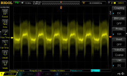
The amp is clearly oscillating - see attached trace. The oscillating gets far worse when connecting a load (4 or 8 ohms doesn't matter). So much worse that my 600 watts smps goes into protection mode when connecting an 8 ohms dummy load.
Any ideas?
First thing I did was to remove the 1 ohms / 2 watt resistors from the power supply rails. I then connected a test speaker (4 ohms) to the amp and switched it on. There was some loud noise coming from the speaker so I switched off the amp immediately.
Removed the test speaker and connected the oscilloscope without any load.
The amp is clearly oscillating - see attached trace. The oscillating gets far worse when connecting a load (4 or 8 ohms doesn't matter). So much worse that my 600 watts smps goes into protection mode when connecting an 8 ohms dummy load.
Any ideas?
Attachments
I continued with the testing after I had setup the amp yesterday.
First thing I did was to remove the 1 ohms / 2 watt resistors from the power supply rails. I then connected a test speaker (4 ohms) to the amp and switched it on. There was some loud noise coming from the speaker so I switched off the amp immediately.
Removed the test speaker and connected the oscilloscope without any load.
The amp is clearly oscillating - see attached trace. The oscillating gets far worse when connecting a load (4 or 8 ohms doesn't matter). So much worse that my 600 watts smps goes into protection mode when connecting an 8 ohms dummy load.
Any ideas?
Is the heatsink properly connected to PSU ground?
Is the problem happening with inputs open or input connected?
Can you upload a couple pictures of the setup?
Is the heatsink properly connected to PSU ground?
Yes it is.
I also tried with the GND disconnected from the heatsink, same result.
Is the problem happening with inputs open or input connected?
Tried with both, same result.
Can you upload a couple pictures of the setup?
There are a few pics in post #817.
But I will take and post some more pics tomorrow.
There are a few pics in post #817.
But I will take and post some more pics tomorrow.
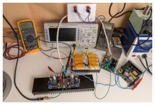
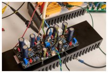
Here is an overview of the setup on my test bench.
From right to left we have:
* The SMPS600ReE power supply. It is a dual 55 volts supply.
* Amp protection board: at present I only use the part of the power supply. It holds the rail fuses (8A) and two bleeder resistors.
* Power supply leads / board: the DC rails are transported from the protection pcb to the amp through this "junction box". You'll notice 4 terminal blocks. I either use this to connect the two 1 ohms resistors in series with the rails (during setup) of bypass the resistors (after setup).
* PeeCeeBee amp on its headsink. Notice the black wire who connects the heatsink with the ground of the supply.
Both GND's are connected to the power supply GND though a separate wire.
Hope this all clear; otherwise just ask if you want more details or clarification.
Attachments
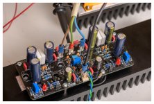
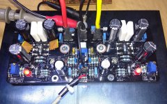
And two more close-up pics.
In the mean time I remove the "junction box" out of the equation. The power supply leads are now running from the protection pcb straight to the amp (with shorter wires). The amp is still behaving the same way (oscillation).
I'm out of ideas.
In the mean time I remove the "junction box" out of the equation. The power supply leads are now running from the protection pcb straight to the amp (with shorter wires). The amp is still behaving the same way (oscillation).
I'm out of ideas.
Attachments

And two more close-up pics.
In the mean time I remove the "junction box" out of the equation. The power supply leads are now running from the protection pcb straight to the amp (with shorter wires). The amp is still behaving the same way (oscillation).
I'm out of ideas.
Are the speakers Gr. connected to the Power Gr? See the picture
Attachments
Are the speakers Gr. connected to the Power Gr? See the picture
Yes, both PGND and SGND are connected to power supply GND by means of separate wires all the way to the power supply. I retain a star connection this way.
I can't connect real speakers at this time due to the oscillation. Connecting the dummy load increases the oscillation quite heavily. My smps is even going into protection mode when connecting a load.
And two more close-up pics.
In the mean time I remove the "junction box" out of the equation. The power supply leads are now running from the protection pcb straight to the amp (with shorter wires). The amp is still behaving the same way (oscillation).
I'm out of ideas.
Which point underboard is the black heatsink cable connected to?
What MOSFETs are you using? Are these genuine?
What is the voltage rating of the pF capacitors?
Which point underboard is the black heatsink cable connected to?
To the SGND connector.
What MOSFETs are you using? Are these genuine?
I hope so; you have shipped them to me 🙂
What is the voltage rating of the pF capacitors?
All 500 volts ceramic caps.
To the SGND connector.
Ok.
Try disconnecting the cable from the heatsink. Use a separate cable and connect the heatsink directly to PSU ground.
I hope so; you have shipped them to me 🙂
Ok. Yes these are genuine.
What VAS and small signal transistors are you using?
All 500 volts ceramic caps.
No problem here.
........
As no external influence affect the oscillation in your case it is an onboard problem, which can be as simple as a loose solder joint or a faulty component. If changing the heatsink cable as suggested doesn't solve the problem then remove the board from the heatsink and carefully inspect the solder joints and test all the BJTs between base-emitter and base-collector.
It's strange because the board set-up readings were normal, and with oscillation the reading should have gone haywire. We'll get the problem sorted soon.
Try disconnecting the cable from the heatsink. Use a separate cable and connect the heatsink directly to PSU ground.
Okay, that did the trick. The oscillation is gone and I can connect the dummy load and the amp behaves nice.
Ran a 1kHz sin trough it and the amplifier behaves normal.
Connected a test speaker and played some music. The amplifier appears functional.
During various tests I changed the GND wiring as following: power supply GND to PGND and then bridge that to SGND (see attached picture).
Is this what you would suggest to use as final wiring or would you run seperate GND wires to PGND and SGND?
As to your question in regards to the transistors I used: I used the transistors as mentioned in the setup guide.
Anyway, thanks for your patience with me. I thought it was a smart move to connect the heatsink to SGND on the PCB...
Attachments
Great that it worked for you.As to your question in regards to the transistors I used: I used the transistors as mentioned in the setup guide.
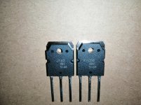
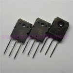
I guess the question really reads "where did you source the transistors?"
There are alot of fakes around.
Great that it worked for you.
I guess the question really reads "where did you source the transistors?"
There are alot of fakes around.
Oh, I misread that. Yes I know, lots of fakes out there.
But I always buy from trusted resources, never buy from ebay or the likes.
Although that is not always a guarantee but I'm quite confident these are genuine. I bought from Conrad.
Okay, that did the trick. The oscillation is gone and I can connect the dummy load and the amp behaves nice.
Ran a 1kHz sin trough it and the amplifier behaves normal.
Connected a test speaker and played some music. The amplifier appears functional.
During various tests I changed the GND wiring as following: power supply GND to PGND and then bridge that to SGND (see attached picture).
Is this what you would suggest to use as final wiring or would you run seperate GND wires to PGND and SGND?
As to your question in regards to the transistors I used: I used the transistors as mentioned in the setup guide.
Anyway, thanks for your patience with me. I thought it was a smart move to connect the heatsink to SGND on the PCB...
Good to know it's working.
In case anyone wonders, here is why it oscillates if SGND is connected to heatsink:
The back of the MOSFTEs are directly connected to output terminal. With the insulator between their metal back and heatsink body, each mosfet creates a very small capacitor between output and heatsink. If the heatsink is left floating i.e. not connected to ground then its body starts acting like an RF radiator and any tiny output noise of sufficiently high frequency is loaded to this radiator via those very small capacitors. The radiated RF is caught by the input and oscillation occurs. Solution is simple - short the antenna i.e. the heatsink to ground. Now, SGND is also ground. So why does connecting the heatsink to this terminal still cause oscillation?
Any length of conductor has some impedance. When the heatsink is connected to the ground via any cable a tiny high frequency noise current flows between output and ground via the aforementioned capacitors. This current creates a tiny noise voltage along the length of the cable due to its impedance; with highest value at the heatsink and zero at PSU ground. If dedicated cable is used for heatsink then this noise voltages does absolutely no harm. But when the heatsink is connected to SGND, and SGND is connected to ground via a cable, at SGND terminal that noise voltage appears at its highest value (only a microvolt or less at the moment of power-on). Now, SGND is connected to input bases via R2 and via this resistor this noise voltage is seen by the input section as a signal to be amplified, and it does just that, presenting the exact noise voltage to the output. The output sends it again back to SGND (now amplified 23 times) and SGND feeds it again to input for amplification. The cycle continues and we have oscillation.
Hi Shaan,
I have a grounding question:
It is important for the heatsink to be connected to the power supply ground (for oscillation reasons). Does this mean that the power supply ground also need to be connected to the rest of the enclosure (for oscillation reasons)?
Let me explain what I’m getting at: in my amplifier builds I tend to completely separate the power supply GND from PE (protection earth). This is to ensure not to create any ground loops. For safety reasons I need to connect PE to the chassis of the enclosure (it is even required by law). But in this case it would mean that power supply GND and PE are connected together (which I don’t like). I know I can use ground breakers but I don’t really like them. I prefer to completely separate GND and PE from each other.
In my current enclosure design I’m electrically isolating the heatsink from the rest of the enclosure. The heatsink will be connected to power supply GND but the power supply GND will be isolated from the rest of the enclosure. The enclosure will be connected to PE. It makes the construction a bit more complex but it is certainly feasible. But I’m wondering if the amp would be subject to oscillation again; hence the question above. (note I'm building mono blocks - one channel in one enclosure). Could you shed some light on this matter?
.... But I’m wondering if the amp would be subject to oscillation again; hence the question above. (note I'm building mono blocks - one channel in one enclosure). Could you shed some light on this matter?
As long as nearby metal pieces (heatsink) are at the same potential as psu GND the amp won't oscillate. Whether it will oscillate when another metal body (the chassis) with a different potential is placed near it, cannot be answered without trying it in that particular scenario. I know it sounds ambiguous but I have seen many amps with the ground and earth isolated to be well behaved while many other amps to go nuts, and also the same amp with isolated gnd and earth to oscillate when powered from one mains outlet and not when powered from a different one. It is my guess that in isolated setups the impedance and HF noise present in the mains earth affect amp stability, particularly if the amp has a wide bandwidth.
I have always interconnected earth and ground via breakers in both stereo and monoblock setups I built and will always recommend that everybody does the same. Safety first, as you already know.
- Home
- Group Buys
- PeeCeeBee V4H GB