It's voltage, so it's 20log not 10log...
Oh right, this isn't power we're talking about, it's just millivoltage
My bad.
An externally hosted image should be here but it was not working when we last tested it.
An externally hosted image should be here but it was not working when we last tested it.
An externally hosted image should be here but it was not working when we last tested it.
An externally hosted image should be here but it was not working when we last tested it.
So, in short, remove one of the 0.01uF caps and change the 0.033uF to .02?
Yes, please explain what I am seeing here. Wayne says you can increase C12 if you would like more bottom end (but would'nt that be the same as increasing C16 as they are parallelled?). I used 0.15uF for C12.
There's not a lot of information below 30Hz in most vinyl -- if you go to a combination approximating 0.47uF for C12 you'll be down 0.1dB @20Hz To make life easy you can use 6.8K and 1k WRT the caps -- if you buy 10 pcs 330nF, there's a high probability you're going to find one ~322nF. Will post the Pearl 2 for fffR in a few minutes!
Yes, please explain what I am seeing here. Wayne says you can increase C12 if you would like more bottom end (but would'nt that be the same as increasing C16 as they are parallelled?). I used 0.15uF for C12.
Yes it would be the same. C12 and C16 form the low frequency cutoff. This is given by 1/2*PI*R*C and with two .1 = about 8 Hz. I would agree that there isn't much info below 30 on most records and many customers of the XP-25 leave the 20 Hz filter on all the time.
Yes, and below 20Hz there is mostly unwanted rumble, so roll-off is useful there. I only wanted to have the curve a bit more linear down to 30Hz. I had no clue however how much to increase C12, so I used a moderate change from 0.1 to 0.15. Maybe 0.22 would have been better. Oh well, The 25Hz rumble on Blade Runner still sounds impressive, so I'll leave it as it is (my speakers don't do sub-30Hz anyway)
What are these simulation graphs that have been posted - looks to me like someone trying to improve the accuracy of the RIAA curve of the stock design? Is that what it is? I don't know the context here, went back several posts and didn't find a beginning to this particular thread, could someone please supply the context?
Also, the FR graphs- a millivolt scale, not the customary dB - is this "accuracy of RIAA" (as would be measured with a sine sweep and an inverse RIAA filter...) or just frequency response of some stage...?
Also, the FR graphs- a millivolt scale, not the customary dB - is this "accuracy of RIAA" (as would be measured with a sine sweep and an inverse RIAA filter...) or just frequency response of some stage...?
ON ANOTHER TOPIC
Has anyone compared the sound of the Pearl One to the Pearl Two? (obviously would have to be done using a cartridge with enough output to properly drive the Pearl One... like a high-output moving coil, for example Dynavector 10X5 or a MM cartride)
Has anyone compared the sound of the Pearl One to the Pearl Two? (obviously would have to be done using a cartridge with enough output to properly drive the Pearl One... like a high-output moving coil, for example Dynavector 10X5 or a MM cartride)
Also, the FR graphs- a millivolt scale, not the customary dB - is this "accuracy of RIAA" (as would be measured with a sine sweep and an inverse RIAA filter...) or just frequency response of some stage...?
I use the Laplace transform with the RIAA values of T3, T4 and T5 -- in Multisim and TINA there are options which allow the insertion of an inverse RIAA curve -- so what you see is the response after it has been transformed. The stock unit is quite good, but if you have an LCR bridge you can probably nail it.
ON ANOTHER TOPIC
Has anyone compared the sound of the Pearl One to the Pearl Two? (obviously would have to be done using a cartridge with enough output to properly drive the Pearl One... like a high-output moving coil, for example Dynavector 10X5 or a MM cartride)
Yes, I have both. The are very similar, as you would expect, being almost the same circuit, where Pearl 2 has more gain (obviously) and is a teeny, tiny, itsy-bitsy bit more refined.
That said, I have no desire to get rid of my Pearl 1, it's breathtakingly quiet and with a top-quality inout transformer may be the perfect thing for low-output MC.
Thanks. Just the info I was looking for.
I will start a separate thread on the "Multi-Pearl2" -- few probably have interest in listening to old records from the 1930's, but I just inherited a bunch of them. The difference between fffR LP and RIAA are pretty small.
The T3/T5 values were derived from various sources on the web, and as Gary Galo pointed out in his Linear Audio article, it might be even better to have a greater multitude of choices:
The T3/T5 values were derived from various sources on the web, and as Gary Galo pointed out in his Linear Audio article, it might be even better to have a greater multitude of choices:
An externally hosted image should be here but it was not working when we last tested it.
Jack, will this require a another particular PCB or do you see a way to do
with some mods to an existing Pearl I or II?
Probably not the best thing on earth, as some more sophisticated phono preamps
sound even better (xOno coming to mind), but certainly a Pearl I + input tranny
is way easier and significiently cheaper to build. Sadly I have never had a chance
to listen to the Pearl II though.
🙂
with some mods to an existing Pearl I or II?
That said, I have no desire to get rid of my Pearl 1, it's breathtakingly quiet and
with a top-quality inout transformer may be the perfect thing for low-output MC.
Probably not the best thing on earth, as some more sophisticated phono preamps
sound even better (xOno coming to mind), but certainly a Pearl I + input tranny
is way easier and significiently cheaper to build. Sadly I have never had a chance
to listen to the Pearl II though.
🙂
Jack, will this require a another particular PCB or do you see a way to do
with some mods to an existing Pearl I or II?
You could probably do it within Wayne's existing boards -- and you don't need to match the myriad of turn-over frequencies which sources like the Rek-O-Cut manual give. I don't have a set of Wayne's boards, so probably dead-bug style with some Teledyne TO-5 relays.
R1 (Lipshitz definition) remains constant in all cases, but you can always "seed" C1 if that's more convenient.
The passive Lipshitz "1C" - network lends itself easily to this kind of manipulation -- you just have to decide what the collection consists of and adopt to your situation. For me, there are several hundred records from the late 1930s, 40's and 50's -- all US -- so the task isn't that difficult.
Hello,
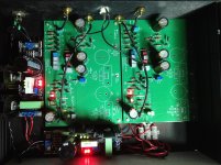
I've have modified my Pearl II to have more gain by reducing R14 value to 300R.
Two questions:
1. Adjusting offset to 0V are we supposed to do it with an input shorted?
2. I would like to calculate overall gain this mod provides with the scope and to see if both channels match in gain. My signal generator can go as low 10mV. Do you, guys, are building voltage dividers to test your phono stages for low input like 0.4 mV signals?
Still oho ping to get a little bit attention here.
Here's a couple of measurements that I have made. To my untrained eye they are deceiving.
After changing the gain resistors I can set DC offset to fluctuate from -60mV to +60mV DC (rough take). How bad is that? Could that be some wiring problem?
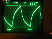
After taking a couple of scope measurements the sine wave at 1kHz 1.1mV shows me that I've got 46 dB (223mV) 😱 gain.
And the square wave doesn't look square at all.
What am I doing wrong?
Here's a couple of measurements that I have made. To my untrained eye they are deceiving.
After changing the gain resistors I can set DC offset to fluctuate from -60mV to +60mV DC (rough take). How bad is that? Could that be some wiring problem?
After taking a couple of scope measurements the sine wave at 1kHz 1.1mV shows me that I've got 46 dB (223mV) 😱 gain.
And the square wave doesn't look square at all.
What am I doing wrong?
Attachments

The square wave is fine - it is going through the RIAA eq and that will do that.
The Sine wave looks ok too.
The DC offset is a problem. Try checking it with the cover on and after everything has warmed up, the airflow around the devices could be making the DC offset go crazy.
If you can't fix it, the options are AC coupling or a DC servo amp to keep the offset stable.
The Sine wave looks ok too.
The DC offset is a problem. Try checking it with the cover on and after everything has warmed up, the airflow around the devices could be making the DC offset go crazy.
If you can't fix it, the options are AC coupling or a DC servo amp to keep the offset stable.
- Home
- Amplifiers
- Pass Labs
- Pearl Two