Hi guys,
First post here despite reading many many threads over the past month or so. Bit of an electronics noob trying to build my first quality usb DAC and having some issues. Maybe you can help...
First of all I bought the aw-d3 kit from www.audioworkshop.com.hk.
I then decided I wanted to use a discrete 3.3v power supply to power the PCM2706 rather than use the dirty USB power. The board already has a ~6.8v regulated supply for the TDA1543 so I built myself a simple circuit to step this down to 3.3v using a voltage divider and BC109. The PCB then had to be modified for self powered operation. This involved removing the PCM2706, cutting traces and grounding the PSEL pin. This all went relatively smoothly and is now complete (despite lifting a few traces when desoldering the PCM2706 :S).
I now faced the issue that 3.3v must NOT be applied to the USB D+ pullup resistor or HOST pin when the USB cable is unplugged to prevent damage to the PCM2706. I borrowed part of the circuit from here and am using a 74HC08 AND gate in exactly the same setup to achieve this.
So in summary my power supply provides a steady 6.8v to the TDA1543 and 3.3v to the PCM2706. 3.3v is applied to the D+ pullup resistor and HOST pin when USB cable is inserted (this is 3.3v sourced from USB power as per dddac.de).
and IT WORKS! ....up to a point.
My problem is that after a few minutes of use (5, 10, 30 or even an hour) my computer reports that the device has been disabled due to possible EMI on the usb line. The drivers are then reloaded and it works again for a few minutes more. This will happen a few times and then my DAC will just 'die' and is no longer detected by the PC. If I then unplug the USB cable (I can leave the power supply plugged in) and leave the DAC sitting for an hour or two it will work again! but only after an hour or so has passed.
I do notice that the little red LED that is wired to the USB 5v (as part of the voltage divider for the AND gate) flickers slightly before the computer complains of EMI and disables it. It also sometimes flickers when the USB cable is first inserted. Of course if the USB 5v drops momentarily (and it flickers) then power to the D+ pullup and HOST pin might be removed which I presume would kill the USB connection. I have tried decoupling the USB 5v right before the AND gate with a ceramic 100n capacitor and also a 43u electrolytic but this doesnt seem to help and in fact the 43u cap stopped the PC detecting it (initial charging current to large?).
I believe these issues are related to instabilities in the USB 5v line however I may be wrong. Maybe the PC is removing USB power to my device when it detects interference? Maybe I have grounding issues. Currently all grounds are linked together.
It also puzzles me that I have to wait some period of time before the device works again as if current is being stored in some capacitor and causing problems. I cant think where though.
Maybe someone has some suggestions as to how I can help stabilise the USB link?
I have of course checked for dry joints/loose connections.
I apologise for rambling on and on!!
The delay sounds temperature related. Does anything get hot?
Just to make sure, did you tie the unused 'HC08 inputs to ground?
Have you tried it on a different computer, or with a different cable?
To isolate the D+ pullup from the +5 behavior, you could insert another logic gate, this one powered from 3.3; but your problem probably lies elsewhere.
Just to make sure, did you tie the unused 'HC08 inputs to ground?
Have you tried it on a different computer, or with a different cable?
To isolate the D+ pullup from the +5 behavior, you could insert another logic gate, this one powered from 3.3; but your problem probably lies elsewhere.
thanks for your reply.
the only thing generating substantial heat is the LT317 for the 6.8v supply although its perfectly within limits and I also have this problem when the thing is cold.
all the HC08's unused inputs are directly connected to ground.
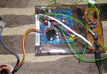
currently i have it setup as shown below with jumper wire linking everything till i build my enclosure. maybe i should shorten the wires somewhat? also the last 15cm of usb cable linking the boards is just 4 core unshielded phone wire :S maybe that has something to do with it? there is a ferrite already on the usb cable but its at the PC end.
i will try and test it with another pc tomorrow.
i notice the flicker that is present when inserting the usb cable comes as the D+ line is connected. the usb connector is shaped such that the GND and 5V lines engage slightly ahead of the data lines and when inserting the cable slowly you can see the flicker as the D+ line meets with the pullup resistor. funny thing is the red led gets brighter momentarily when this occurs.
i'm going to try and digitise my schematic in eagle so you can properly see what's going on.
the only thing generating substantial heat is the LT317 for the 6.8v supply although its perfectly within limits and I also have this problem when the thing is cold.
all the HC08's unused inputs are directly connected to ground.
currently i have it setup as shown below with jumper wire linking everything till i build my enclosure. maybe i should shorten the wires somewhat? also the last 15cm of usb cable linking the boards is just 4 core unshielded phone wire :S maybe that has something to do with it? there is a ferrite already on the usb cable but its at the PC end.
i will try and test it with another pc tomorrow.
i notice the flicker that is present when inserting the usb cable comes as the D+ line is connected. the usb connector is shaped such that the GND and 5V lines engage slightly ahead of the data lines and when inserting the cable slowly you can see the flicker as the D+ line meets with the pullup resistor. funny thing is the red led gets brighter momentarily when this occurs.
i'm going to try and digitise my schematic in eagle so you can properly see what's going on.
Attachments
ok i have made some progress with this.
i have removed the short length of phone wire i was using to connect up the usb and put another ferrite on the cable - still i have problems. i modified the HC08 to run of my 3.3v supply - still problems.
but i have found that if i unplug the rca jacks to my amp the issue seems to go away. somehow the link with the amp is introducing interference.
grounding issues? that is one area i have no knowledge at all really.
ive been reading this thread which seems to cover the same issue.
I'm also going to try putting 22pF capacitors on the D+/- pins to ground right at the chip as suggested here
also the issue with having to wait an hour before it works again seems to be a fud as it always seems to work again after unplugging it and inserting it again.
problem also present with different cable and another laptop.
problem also present with different cable and another laptop.
bah now it seems the thing has died altogether 🙁
might enquire about getting another board sent out from audioworkshop but who's to say i wont have the same problems all over again.
does anyone have any suggestions how I can get a reliable, working DAC with the minimum extra expenditure?
might enquire about getting another board sent out from audioworkshop but who's to say i wont have the same problems all over again.
does anyone have any suggestions how I can get a reliable, working DAC with the minimum extra expenditure?
IIRC there was someone tried both bus powered and self powered and found there is no improvement though the datasheet claims to have some.
pcm270x may have 4 good sets of separate LDO regulators on board already. the datasheets shows 120dB noise floor and from my listening test through headphones, pcm2707 bus powered is very quiet and works just fine. I didn't notice any noise at all.
If you would like to try and compare, I can supply the board /components. 🙂
thanks Archwn.
to be honest i think your right and i'm pretty sure i couldn't tell the difference between bus and self powered especially with my speaker setup. suppose i was just tempted by the numbers and thought i'd give it a go as a challenge for myself, guess that gamble didn't pay off.
what i did hear of the DAC was mostly the output from the TDA1543 which i was really happy with. was going to use this as an upgrade over my creative sound blaster usb soundcard which seems subdued in the midrange around 3-4kHz ish. the 1543 was 1000 times better and sounded really sweet to my ears. would love to hear the pcm's output too.
thanks for your offer of boards, do you have a schematic for your design?
i thought i'd give my dead board another try to day - plugged it in and its working again!?!? :S that's despite me failing to get it to respond at all last week. this thing is seriously puzzling me, why does leaving it alone for a day/week suddenly fix it!? needless to say it lasted all of 13minutes and then disconnected itself again.
its so frustrating having something so close to perfect and yet utterly unreliable.
Code:
Apr  5 15:02:52 i2648 kernel: [35155.324000] usb 1-2: configuration #1 chosen from 1 choice
Apr  5 15:02:52 i2648 kernel: [35155.356000] input: Burr-Brown from TI               USB Audio DAC    as /class/input/input15
Apr  5 15:02:52 i2648 kernel: [35155.356000] input: USB HID v1.00 Device [Burr-Brown from TI               USB Audio DAC   ] on usb-0000:00:1d.0-2
Apr  5 15:02:52 i2648 kernel: [35155.528000] usbcore: registered new interface driver xpad
Apr  5 15:02:52 i2648 kernel: [35155.528000] /build/buildd/linux-source-2.6.22-2.6.22/drivers/input/joystick/xpad.c: driver for Xbox controllers v0.1.6
Apr  5 15:15:52 i2648 kernel: [35935.328000] usb 1-2: USB disconnect, address 5
Apr  5 15:15:52 i2648 kernel: [35935.440000] usb 1-2: new full speed USB device using uhci_hcd and address 6
Apr  5 15:15:52 i2648 kernel: [35935.640000] usb 1-2: configuration #1 chosen from 1 choice
Apr  5 15:15:52 i2648 kernel: [35935.640000] snd-usb-audio: probe of 1-2:1.0 failed with error -5
Apr  5 15:15:52 i2648 kernel: [35935.644000] input: Burr-Brown from TI               USB Audio DAC    as /class/input/input16
Apr  5 15:15:52 i2648 kernel: [35935.644000] input: USB HID v1.00 Device [Burr-Brown from TI               USB Audio DAC   ] on usb-0000:00:1d.0-2
Apr 5 15:16:44 i2648 kernel: [35987.744000] usb 1-2: USB disconnect, address 6i think i might be getting some EMI through the power lines as when i switch on my amp (regardless of whether its plugged in to the DAC or not) it disconnects the DAC from the computer and grumbles about EMI.
does anyone fancy taking a look at my power supply schematic? i'd love to hear your comments and suggestions for better isolating it from mains noise.
does anyone fancy taking a look at my power supply schematic? i'd love to hear your comments and suggestions for better isolating it from mains noise.
Attachments
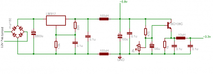
Not sure if this of any cause, but at least it is not ok --> the 10uH inductor and 100nF are resonating at 158kHz with 25dB amplification. you should ampen this sufficiently with 100uF ....
ok! thanks so much. i really don't know much about the theory here so that's just the kind of information i'm after.
i have updated my schematic. when you say dampen it with a 100uF do you mean instead of the 100nF or in parallel with it as i have drawn?
i am also thinking of replacing the cheap 100uF electrolytics with ELNA cerafine 47uF caps i have as they are of better quality - would this be ok?
maybe i should just remove the inductor? i'm not sure its needed.
i really appreciate your help.
Attachments
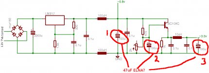
parallel is ok when you use a normal electrolyte. otherwise you can replace it by a low esr one
the 47uF Elnas look fine as well. the value is not so critical
Try first adding a capacitor, before you change everything 😉
The inductor is just great, keeps hf noise away...
the 47uF Elnas look fine as well. the value is not so critical
Try first adding a capacitor, before you change everything 😉
The inductor is just great, keeps hf noise away...
I don't like the placement of the two 100uH inductors. If you're aiming to filter out mains noise, the filtering should occur upstream of the LM317, IMO. Look into a "CLC" or "pi" filter.
ok, first of all i tried adding that 47uF cap across the 3.3v output. left the rest the same. sadly although it worked for a while the same problems still remain and the device disconnects itself occasionally. maybe an improvement, its hard to say.
mako1138: i then thought about what you wrote. those two inductors were just an afterthought of mine. the 6.8v supply is on one pcb from the kit and the rest is on a board of mine so i just threw those inductors between them and added some caps. decided to take them out and see what happens. seems to have made things worse. i can see adding them before the lm317 would be ideal but that would mean ditching one pcb.
i've looked at pi filters before but choosing appropriate values for all the components got to complex. and i guess i want fairly broadband filtration to get rid of the EMI rather than just targeting the 120Hz rectified mains hum?
again i seem to be stuck. i'm going to put the inductor back on the ground line after the 6.8v supply and give things another go. i got the impression it was advantageous to have all grounds connected through ferrites/inductors so thats what i was going for there. i also have 100uH inductors connecting USB ground and the USB shielding to the ground plane.
i did notice my problems appeared to go away (it ran ok for 2.5hrs) when i fed regulated +-6v from another supply in place of the torroid so that does suggest its a power supply problem.
Thanks so much for all your time and help guys.
Ok i seem have (partly) solved this. I resoldered the PCM2706 and that seems to have stabilised the USB connection - must have been a dry joint all along.
I do still have problems with it disconnecting when other appliances (cooker/amp etc) in my house are switched on/off. I'm running it though one of those plug in mains RFI filters however it hasn't helped.
Does anyone have any suggestions for beefing up my power supply to protect against these transients and noise?
I'm a bit suspicious of all of the chokes you mention in your ground and common lines, these should be common mode types in conjunction with the other associated signal. Conventional chokes just raise the HF impedance to ground and could very well be at the root of some of the problems you are having. Conventional chokes should only be used on supply rails...
If you want to filter the power coming into your supply place the chokes after the rectifiers and before the first filter caps. Use a single common mode choke for the +/- coming out of the rectifier and place a single choke in the + lead after that. Place a small ceramic cap (0.1uF) right across the input to the cm choke, and another right after the standard choke.
Several vendors now sell cm chokes that incorporate a certain amount of deliberate leakage inductance in order to obviate the need for a second choke - you can use one of these too.
One other thing I would place that 10uH choke before the transistor, and its voltage setting network not in the emitter circuit which normally has pretty low output impedance. I would add a very small resistor in series with the collector to limit charging current to that 100uF cap. (At time 0 it looks like a dead short.)
The cap across the 1.5K resistor setting the output voltage of the LM317 should be at 10uF in order to get the good ripple and noise rejection the LM317 is capable of.
For best performance you want at least 5V drop across the LM317 - that improves the performance of the internal error amplifier and reduces the likelihood of line transients propagating through the regulator. Current is not very high so even higher voltages are fine.
Can you post some pix of how you have implemented the supply and mods to the usb receiver? This will help us determine if you have done something really bad.. 😀
thanks kevin some great suggestions there!
i see you point about using conventional chokes on the ground lines and increasing HF impedance to ground, i'm gonna ditch them. i'll leave 100uH chokes on the USB power rails (as per the AW-D3 kit).
sorry you lost me there :S
that makes sense to me and is an easy fix. i'll give it a go.
ok cool i think i remember reading that in the datasheet. i'm just using the value supplied with the AW-D3 kit but can easily change it. i'll maybe have to order in a suitable cap.
Yep i think i'm ok on that front. My 12v torroid at such light load is giving more like 18v DC after the regulator.
I'll try and upload some pics of my mods shortly altho my shoddy work and bad soldering is rather embracing 😛
Its good to have some things to be getting on with!
i see you point about using conventional chokes on the ground lines and increasing HF impedance to ground, i'm gonna ditch them. i'll leave 100uH chokes on the USB power rails (as per the AW-D3 kit).
and its voltage setting network not in the emitter circuit which normally has pretty low output impedance
sorry you lost me there :S
I would add a very small resistor in series with the collector to limit charging current to that 100uF cap. (At time 0 it looks like a dead short.)
that makes sense to me and is an easy fix. i'll give it a go.
The cap across the 1.5K resistor setting the output voltage of the LM317 should be at 10uF
ok cool i think i remember reading that in the datasheet. i'm just using the value supplied with the AW-D3 kit but can easily change it. i'll maybe have to order in a suitable cap.
For best performance you want at least 5V drop across the LM317
Yep i think i'm ok on that front. My 12v torroid at such light load is giving more like 18v DC after the regulator.
I'll try and upload some pics of my mods shortly altho my shoddy work and bad soldering is rather embracing 😛
Its good to have some things to be getting on with!
In regards to that 10uH choke referring to your schematic place it between the 0.1uF cap and the 470 ohm resistor.. Basically you want it just before the transistor regulator circuitry. The cap connected to the base of the BC109 should be bypassed by a very good ceramic to maintain effectiveness at high frequencies.
- Status
- Not open for further replies.
- Home
- Source & Line
- Digital Source
- PCM2706 USB DAC - Interference/Temperamental Connection