That being said, while the ESS are great parts; getting datasheet distortion performance is not a simple task. if you are struggling to make the PCM do its job, designing a board to get another >10dB over the max capable from the PCM will be even more of a struggle.
On another note, @pandaemonium9, unless you are in a hurry, or plan on building many dacs, you might consider waiting a few months for AKM to come back online with a possible updated AK4499
On another note, @pandaemonium9, unless you are in a hurry, or plan on building many dacs, you might consider waiting a few months for AKM to come back online with a possible updated AK4499
That's a fairly typical output, especially the peak at 1K. Overall, it's not bad but can be improved with better filtering. Some Sample Rate Converters and DSPs often have filters or similar to minimize those components (at 1K, 2K, 3K, 4K) and it's still in the digital realm. The rising curve starting at 10K is typical too. The master clock can cause problems. With 4x over sampling you can expect to see the three additional peaks from 1K. A high quality external master clock (PLL) can be helpful to help alleviate jitter problems. Make sure you use a high quality voltage regulator for the external clock (I use LP2982 and a PLL1707 for the clock, another common D.I.Y. clock is the "o2"). Tuning the I²S track lengths can help too, even though its low frequency, and if your DAC output has differential (not balanced) circuity, it's essential to tune the differential tracks. I tune (as best as possible) to within 0.01mm to 0.05mm, both in length and symmetry.I have tried to use 4-layer PCB and low-noise LDO. The results are shown in the figure below. LDO suppresses the sound of transformer very well. The default circuit in the manual is used, but it is far from the nominal performance in the manual. I don't know what's wrong, or the performance of this circuit is like this. If you want to see more details, you can take a look at my thread.
Considering the low noise of good op-amps, it's no problem to construct a 4th order (two op-amps) to an 8th (four op-amps) or higher LP filter. The LP filter is going to have lower harmonics amplified, and despite the oscillator frequency, it will start at 1K due to the DAC topology. The filter roll-off of the LP filter will create a lower harmonic noise starting and rising at 10K, and a lesser magnitude lower harmonic starting at 100Hz and rising to DC (the DC is filtered out by the DAC. Usually). If the internal filter is disabled and you haven't included your own, that may not be the case, then, woe to thy tweeting devices! The internal filter can usually be disabled, a good filter won't fit in the package, especially parts like mica, polystyrene, or PPS capacitors. Furthermore, a great deal of noise is generated outside of the DAC anyway. It generally doesn't hurt to use both.
I'm just wondering about inverting the 1K spike and using it for cancellation (most of it), it's probably a lot more difficult than I think.
The ESS parts look good, but they emphasize all the filters they use, and give very little information about them, in fact they're intentionally withholding information and even have usage rights and N.D.A.s! I'd still like to try some though, I can't comment unless I try them (and maybe not then depending on the usage/disclosure rights). Maybe they dropped the whole N.D.A. thing now, but when I first seen it a few years back, I immediately left the web site and didn't look back until recently. I couldn't even get datasheets of any kind, just brochures back then. You had to fill out a form for technical information and someone would get back to you. One thing that bothers me about the ESS DACs is that they use the word PRO but have output levels better suited to consumer/Semi-pro level outputs (as far as I can tell), requiring more gain and thus noise. I'd rather attenuate a high signal (with a T or H-bridge as needed) than amplify a low signal. Pro is at +4dBu, not too bad, the German ARD standard is at +6bBu, and Japan (some Yamaha products and probably others) have gone extreme with +8dBu to +24dBu! The ESS datasheet(?) shows a cutesy schematic without any component values and there's next to no information about the DAC output specifications. There's tonnes of usage information about all the filters though. Maybe someone has a link to some more extensive information, or maybe something like a "developer board user's guide" with a real schematic if there is one?
Weather it's voltage or current conversion, there's going to be noise problems, there's no avoiding that (maybe), just minimizing it, and most solutions I have seen are pretty much the same (in characteristics, not noise levels). I have plans to work on an FPGA as a pre or maybe a partly post (using very high speed transistors) processor of sorts to eliminate those spikes and extrapolate the the missing data; mathematically or from input data. That is if anything exists after the digital LP filter It sounds like a lot of work though!
Ya, I'm in no big hurry, I have a large project going on at the moment, it's got 8 schematics sized at A2, hopefully it should be done by summer.That being said, while the ESS are great parts; getting datasheet distortion performance is not a simple task. if you are struggling to make the PCM do its job, designing a board to get another >10dB over the max capable from the PCM will be even more of a struggle.
On another note, @pandaemonium9, unless you are in a hurry, or plan on building many dacs, you might consider waiting a few months for AKM to come back online with a possible updated AK4499
I've been looking at the AK4499 and it definitely appears worthwhile! It looks like mono mode (stereo) can be done with one AK4499 as far as I can tell!
Yeah, extremely demanding and a bit limiting on the IV stage though the AKM parts. in 2 channel or fully mono setup, they require the IV stage to parse a huge amount of current, a bit like the 9038PRO. This forces your hand a bit with opamp choice, or means you must construct a composite amp, or discrete/IC composite for IV.
regarding the ESS datasheets, most, but not all datasheets are now public and have been for a couple years now. As always they are a bit lacking in their quality, but that has always bee the case, even when youve signed the NDA. to get truly good support it appears you must be a big customer; but they are not exactly alone in this type of behaviour these days.
regarding the ESS datasheets, most, but not all datasheets are now public and have been for a couple years now. As always they are a bit lacking in their quality, but that has always bee the case, even when youve signed the NDA. to get truly good support it appears you must be a big customer; but they are not exactly alone in this type of behaviour these days.
Good advice on the clocking. My pick for his problems is AVCC regulator misbehaving with some kind of resonance in the output. those TPS regulators are fairly picky with input and output capacitance (value and type) and their PSRR degrades at higher FS and unless this is taken care of, the clock may bleed through and cause what we see here. I would generally have the mclk onboard too.
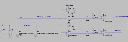
here is the 9038PRO 8ch board/application schematic.
here is the 9038PRO 8ch board/application schematic.
Attachments
I ran across an interesting looking part that I may have to play with: SSM6322 (Analog Devices). It's an I/V V/V converter for DAC outputs. The specifications are pretty decent, and they suggest it for pro applications. Built in two-pole LP filter, 4mm x 4mm package! Able to drive low loads, down to 16Ω I think it said. The graphs look good, but graphs tend to be misleading. I wonder if it would be friendly with my go-to LME49600 headphone buffers? Even if it's not the best part (who knows), it may simplify things for some people. Has anyone tried this part?
- Home
- Source & Line
- Digital Line Level
- PCM1794 vs PCM1793 balanced output?