

A demo with a boxed version
(raspberry pi3, volumio2, spotify)
https://www.youtube.com/watch?v=WEPui-DQyR8
we are waiting "coax/optical input to i2s pcbs"
planing to unbalanced to balanced converter with opa1632 then finally mcu+graphic oled lcd
(raspberry pi3, volumio2, spotify)
https://www.youtube.com/watch?v=WEPui-DQyR8
we are waiting "coax/optical input to i2s pcbs"
planing to unbalanced to balanced converter with opa1632 then finally mcu+graphic oled lcd
Wouldn't it be better to give that gain needed by the buffer instead, and keep the I/V resistance as seen by the 1704 low.
As I also use no active preamp with no gain and my output buffer after the I/V stage has the gain needed to give the >2v at the output.
Cheers George
Yes, you are right. I reduced the I/V resistance from 2.7 k to 1.35 k. I added some gain to opa1632 unbalanced to balanced stage. Result: Awsome 🙂
Thank you..
coax/opt to i2s converter pcb has arrived;
An externally hosted image should be here but it was not working when we last tested it.
Unb. to Bal. conv. with opa1632;
Any reason for balanced , apart for use with balanced preamp? Seems unneccessary?
Any reason for balanced , apart for use with balanced preamp? Seems unneccessary?
Hi supra;
short answer; my system fully balanced. Balanced gnd free design lower noise, high S/N ratio.
There's one more way; I can use 2 pcm1704 pcb (four pcm1704) but it's very expensive solution to unbalanced/balanced conv. 🙂
Yes, you are right. I reduced the I/V resistance from 2.7 k to 1.35 k. I added some gain to opa1632 unbalanced to balanced stage. Result: Awsome 🙂
Thank you..
1.35k? I meant 15ohm and double or triple the gain of the buffer. As current output dacs love to see an almost short to get the best from them.
Cheers George
Hi George;
Do you mean you want to say 15 ohm at discrete iv output?
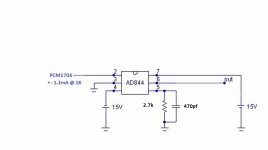
AD844 iv;
our discrete iv (Pedja Rogic's Inspired by ad844)

(not 3.3 k now, 1.35 k)
I have heard about 25-30 gain circuits (SRPP Tube) at the output by using passive iv and 30-50 ohm iv resistance. But is this also true for discrete iv? And 15 ohm and 1.2 ma (pcm1704 I out) need ~x157 gain for 2v rms out. isn't it right?
Thank you
Do you mean you want to say 15 ohm at discrete iv output?
AD844 iv;
An externally hosted image should be here but it was not working when we last tested it.
our discrete iv (Pedja Rogic's Inspired by ad844)
(not 3.3 k now, 1.35 k)
I have heard about 25-30 gain circuits (SRPP Tube) at the output by using passive iv and 30-50 ohm iv resistance. But is this also true for discrete iv? And 15 ohm and 1.2 ma (pcm1704 I out) need ~x157 gain for 2v rms out. isn't it right?
Thank you
In the meantime, we have V3.0 cards. There are no revisions etc here. I just added the spdif part to the same card, I added a bit more input options (coax and opt) and completely software (mcu) control. I have added the module with wm8805 (for direct i2s via raspberry pi), there is also an optional src4192 sample rate converter. With Bypass, 24/96 and 24/192 upsampling options. It's about the same size, but it's a pretty tight card.
v2 & v3

An externally hosted image should be here but it was not working when we last tested it.
v2 & v3
Hi George;
Do you mean you want to say 15 ohm at discrete iv output?
AD844 iv;
An externally hosted image should be here but it was not working when we last tested it.
our discrete iv (Pedja Rogic's Inspired by ad844)
An externally hosted image should be here but it was not working when we last tested it.
(not 3.3 k now, 1.35 k)
I have heard about 25-30 gain circuits (SRPP Tube) at the output by using passive iv and 30-50 ohm iv resistance. But is this also true for discrete iv? And 15 ohm and 1.2 ma (pcm1704 I out) need ~x157 gain for 2v rms out. isn't it right?
Thank you
No, the load the PCM1704 sees with a triple stack AD844 on it's pin 2 is 15ohm. The resistor you've circled (1.5kohm) is not the I/V resistor it's the TZ "gain" resistor.
Cheers George
Hi George,
I think, ad844 with no feedback is using current out (pin 5) and need I/V resistors to TZ pin. The gain (output voltage) still adjust with this I/V resistor. Like our discrete I/V (
similar of AD844 simplified schematic.)
Pedra Rogic's discrete IV stage document (we use this schematic);
http://www.diyaudio.com/forums/blog...-out-production-pedja-rogic-ddnf-iv-stage.pdf
I dont know (I have not measured and simulated) our iv stage "input" impedance.
Datasheet page 13 says AD844 pin 2 input impedance is around 50 ohms.
Pedra Rogic's AYA DAC. TDA1541A non-oversampling DIY DAC document;
Full document is here;
https://www.google.com.tr/url?sa=t&...EBNiV4dJ3f0bZususOu_cQ&bvm=bv.149397726,d.d24
Thank You,
I think, ad844 with no feedback is using current out (pin 5) and need I/V resistors to TZ pin. The gain (output voltage) still adjust with this I/V resistor. Like our discrete I/V (
similar of AD844 simplified schematic.)
Pedra Rogic's discrete IV stage document (we use this schematic);
http://www.diyaudio.com/forums/blog...-out-production-pedja-rogic-ddnf-iv-stage.pdf
I dont know (I have not measured and simulated) our iv stage "input" impedance.
Datasheet page 13 says AD844 pin 2 input impedance is around 50 ohms.
An externally hosted image should be here but it was not working when we last tested it.
Pedra Rogic's AYA DAC. TDA1541A non-oversampling DIY DAC document;
An externally hosted image should be here but it was not working when we last tested it.
An externally hosted image should be here but it was not working when we last tested it.
Full document is here;
https://www.google.com.tr/url?sa=t&...EBNiV4dJ3f0bZususOu_cQ&bvm=bv.149397726,d.d24
Thank You,
From the data sheet the pin two of the 844 is 50-65ohms input impedance, stack 3 and it's around 15ohm.
"INPUT CHARACTERISTICS: Input Resistance Negative Input 50-65ohms."
Cheers George
"INPUT CHARACTERISTICS: Input Resistance Negative Input 50-65ohms."
Cheers George
Attachments
Last edited:

It's a bit unclear for me, will you offer boards, with the PCM1704 ?
Anyway; project is looking very good indeed!
Jesper.
Anyway; project is looking very good indeed!
Jesper.
As far as I read, this is still under development and need some bugs to work out ? I am awaiting for the final result 😀
Development is finished. All test is ok. There is no any bug. Just working that all parts collects into box sensitively with good wires. And @mp3dragon like to add some cosmetics parts ( screen, button, input sellector etc.)As far as I read, this is still under development and need some bugs to work out ? I am awaiting for the final result 😀
Last edited:
I continue to add wiring and regulator circuits. All analog and digital (before adm7150) supplys are shunt reg. Raspberry Pi v3 supply is linear psu. I am planning two version of operation panel. One of simple, will only have input select button and leds. Other's will have oled graphic lcd, remote control and volume control.


- Home
- Source & Line
- Digital Line Level
- PCM1704 Diy dac+ discrete i/v+ valve buffer