Well, in my opinion, as late as possible, and with negative feedback. I remember that some work was done on a digital amplifier with negative feedback (called class Z or so). This was 2003 or so, and newer / better methods may have come up since then.
http://www.cdd.ru/repository/SCCLZBR1.pdf
It would be nice if anyone could find the white paper for the above.
http://www.cdd.ru/repository/SCCLZBR1.pdf
It would be nice if anyone could find the white paper for the above.
Patent US 7.626,519 B2 certainly has some math in it. Of interest in my particular quest, are the statements "(PCM to) PWM audio processor 20 may be implemented by way of one or more software routines executed by a digital signal processor integrated circuit, or a digital signal processor “core” within a larger scale integrated circuit."
And "This ability to select or vary the PWM period to which a PCM signal is modulated is especially beneficial in some applications, such as digital audio systems. The effects of PWM interference ... can also be reduced, according to this invention, by modulating the PWM frequency according to a “spread-spectrum" pulse-width modulation approach, thus spreading the interfering energy over a wide frequency band."
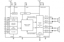
The TAS5825 spec has a couple corroborating statements "the audio path of the TAS5825M consists of a digital audio input port, a digital audio path, a digital to PWM converter (DPC), a gate driver stage, a Class D power stage..." Also - and pretty much a discerning feature of the patent; "The TAS5825M supports Spread Spectrum with triangle mode". You enable it by setting a register value.
I'm wondering more and more if the TAS5825M is the product embodiment of the tech described in patent US 7.626,519 B2...
And "This ability to select or vary the PWM period to which a PCM signal is modulated is especially beneficial in some applications, such as digital audio systems. The effects of PWM interference ... can also be reduced, according to this invention, by modulating the PWM frequency according to a “spread-spectrum" pulse-width modulation approach, thus spreading the interfering energy over a wide frequency band."
The TAS5825 spec has a couple corroborating statements "the audio path of the TAS5825M consists of a digital audio input port, a digital audio path, a digital to PWM converter (DPC), a gate driver stage, a Class D power stage..." Also - and pretty much a discerning feature of the patent; "The TAS5825M supports Spread Spectrum with triangle mode". You enable it by setting a register value.
I'm wondering more and more if the TAS5825M is the product embodiment of the tech described in patent US 7.626,519 B2...
In 2007, phase_accurate claimed that this is the patent: https://worldwide.espacenet.com/publicationDetails/originalDocument?CC=JP&NR=2006174421&KC=&FT=E# (in Japanese and English). It's a mixture of digital and analogue stuff, essentially a noise shaping loop with an analogue input and a digital feedforward path.Well, in my opinion, as late as possible, and with negative feedback. I remember that some work was done on a digital amplifier with negative feedback (called class Z or so). This was 2003 or so, and newer / better methods may have come up since then.
http://www.cdd.ru/repository/SCCLZBR1.pdf
It would be nice if anyone could find the white paper for the above.
Thanks for the link. It's a very reasonable and educated guess, as many details like clock frequency of 108MHz etc. also seem to match up very well with NAD documents (e.g. this one). According to the patent, the method appears to compare the two PWMs together (unlike regular amplifiers) to generate the system error, which is probably where the name DDFA comes from.
To the OP: Since you're out here to compare all available methods...
Direct digital is just one school of thought, there's also the Open Loop take on Class-D amps, that has also resulted in some commercial products like DDX amplifiers and others like TAS5825 mentioned by jjasniew above.
However, I strongly believe that negative feedback is absolutely necessary unless it's an itsy-bitsy power application like mobile, laptop speaker etc.
Oh yes, sorry.
Nevertheless, the feedback is not POL as it is tapped from before the filter. And it's interesting that the US patent 7,626,519 B2 mentioned by jjasniew doesn't seem to show anything like that, not at least from the drawings in the patent document.
Dear OP, you may also read this DDX whitepaper:
http://www.apogeebio.com/ddx/PDFs/AN-14.pdf
Last edited:
Indeed. The TAS5825 block diagram fits better with the patent US7262658B2 that jjasniew referred to in another thread.
Yes, that's more like it and it seems jjasniew is really after the TAS5825, matching it up with the content in various patents, in an attempt to understand all the nuts and bolts within.
Anyway if going all digital, sigma-delta seems to be the way to go, as it has pulse output for switching operation, noise shaping for resolution and feedback (pre/post filter) for further error correction. The open-loop methods like DDX, though used in a lot of HTIB products, are rather hard to digest.
Anyway if going all digital, sigma-delta seems to be the way to go, as it has pulse output for switching operation, noise shaping for resolution and feedback (pre/post filter) for further error correction. The open-loop methods like DDX, though used in a lot of HTIB products, are rather hard to digest.
The digital sigma-delta modulators used in DACs only have feedback from the digital output signal. If you want feedback from the analogue signal (pre- or post-filter), you need a fast ADC in the noise shaping loop.
Yes, but once the A/D conversion is done, it's all numbers and the digital control system is essentially free of most issues present within a hardware controller. So it may not be wrong to say that the advantages potentially outweigh the requirement for an ADC. The ADC is also a trivial thing as more complicated components such as DSPs with multiple embedded ADCs have become commonplace in audio.
To me, the DDFA (NAD) looks like a neatly done thing, but I'm not sure what others think of it.
To me, the DDFA (NAD) looks like a neatly done thing, but I'm not sure what others think of it.
Maybe we don't see a full loop out to the speaker binding posts due to not so much lack of good ADC but the brutal level of errors and potential unstable loop situations? Would it suffer the same problems as to why bass motional feedback only works up to say 100Hz or so...
//
//
TI used to make the TAS5010 (datasheet attached) which was a PCM to PWM converter. The modulator is described as:
"The interpolation filter output is sent to the modulator. This modulator consists of a high performance fourth order digital noise shaper and a PCM-to-PWM converter. Following the noise shaper, the PCM signal is fed into a verylow distortion PCM-to-PWM conversion block, buffered, and output from the chip. The modulation scheme is based on a 2-state control of the H-bridge output"
This sounds like a delta sigma converter to me.
In SLAA117A* this patent is referenced:
https://patents.google.com/patent/AU2567297A/enI think this is the same as the european patent that I have attached but I don't have time to look at it right now.
*Also in this application note it is mentioned that the switching rate of the modulator is set by the up sampled sample frequency of 384khz.
Attachments
That's the feed-forward (estimation and compensation) method to correct errors instead of feedback. However, the model that the estimate is based on needs to be fairly accurate.
I guess you're referring to the loss of phase margin (and potential instability) due to the phase-shift of the second order LC filter.
In classical control, both the plant and the controller are represented by LTI transfer functions that are not allowed to change, even if the external disturbances to the system are known to change violently. Besides, any attempts made to stabilise the system using predictive (PD) control usually results in excessive overshoots, ringing etc.
On the other hand, a variable structure nonlinear controller is allowed to vary / switch the control law (e.g. loop gain, pole/zero freq etc.), as soon as the state variables indicate the onset of instability. Thus, the instability limitations of classical control are not equally applicable to non-linear control techniques.
And one of the main advantages of digital control systems is indeed the ease of implementation of complicated non-linear control techniques. Of course, analogue implementations are also possible (e.g. hysteresis control), but often involve much simpler control laws.
Maybe we don't see a full loop out to the speaker binding posts due to not so much lack of good ADC but the brutal level of errors and potential unstable loop situations? Would it suffer the same problems as to why bass motional feedback only works up to say 100Hz or so...
I guess you're referring to the loss of phase margin (and potential instability) due to the phase-shift of the second order LC filter.
In classical control, both the plant and the controller are represented by LTI transfer functions that are not allowed to change, even if the external disturbances to the system are known to change violently. Besides, any attempts made to stabilise the system using predictive (PD) control usually results in excessive overshoots, ringing etc.
On the other hand, a variable structure nonlinear controller is allowed to vary / switch the control law (e.g. loop gain, pole/zero freq etc.), as soon as the state variables indicate the onset of instability. Thus, the instability limitations of classical control are not equally applicable to non-linear control techniques.
And one of the main advantages of digital control systems is indeed the ease of implementation of complicated non-linear control techniques. Of course, analogue implementations are also possible (e.g. hysteresis control), but often involve much simpler control laws.
Analogue class-D amplifiers have also been commonplace for a couple of decades.Yes, but once the A/D conversion is done, it's all numbers and the digital control system is essentially free of most issues present within a hardware controller. So it may not be wrong to say that the advantages potentially outweigh the requirement for an ADC. The ADC is also a trivial thing as more complicated components such as DSPs with multiple embedded ADCs have become commonplace in audio.
To me, the DDFA (NAD) looks like a neatly done thing, but I'm not sure what others think of it.
Audio ADCs are usually sigma-delta modulator ADCs, which are typically made of a chain of integrators, state variable limiting or reset circuitry, a quantizer, one or more feedback DACs and possibly feedforward paths. That's not too different from the circuitry used in the TI analogue PWM generation block in US7262658B2, so I would expect analogue imperfections of that circuitry to be of the same order of magnitude as imperfections in sigma-delta ADCs.
I guess you are right about it being easier to make a complicated control loop in a digital than in an analogue implementation. On the other hand, if the feedback ADC is a sigma-delta ADC, you have to think carefully about the frequency planning to ensure that its out-of-band quantization noise does no harm. You can't just suppress it with a steep filter, because you probably don't want a steep filter's phase shift in the loop.
For the record, I never designed a class-D amplifier. I have worked on sigma-delta ADCs and DACs, the latter with and without embedded pulse width modulator.
Audio ADCs are usually sigma-delta modulator ADCs, which are ..... not too different from the circuitry used in ......US7262658B2, so I would expect analogue imperfections of that circuitry to be of the same order of magnitude as imperfections in sigma-delta ADCs.
Aren't those imperfections much more benign ones when compared to the gross errors of the power stage? If yes, then I think it's OK, as that's probably the closest you could get.
It's also possible to use two feedback loops (cascaded control), with an outer (slower) loop to handle the post-filter error, while the inner (faster) loop compares the pulses themselves, compensating for the faster pulse-width errors. The net system error then needs to be scaled (to maximise bits), integrated and a/d converted to drive the digital system.
.... you have to think carefully about the frequency planning .... you probably don't want a steep filter's phase shift in the loop.
Yes, this feedback needs to be much faster in order to preserve stability. However, people usually slow down the forward path instead, by having intergators etc. What about the flash-type ADC? Isn't that supposed to be faster, or is it already obsolete?
For the record, I never designed a class-D amplifier. I have worked on sigma-delta ADCs and DACs, the latter with and without embedded pulse width modulator.
Dear Marcel, I'm the exact opposite of you! I have never designed an ADC/DAC (with or without embedded pulse width modulation) but have worked on power converters including Class-D amplifiers and motor drives.
Flash ADCs are indeed very fast, but they need n - 1 comparators for n output codes, so you need 65535 comparators for 16 bit resolution. That gets a bit expensive in terms of chip area.
You could use a SAR or a pipelined ADC instead. Compared to sigma-delta ADCs, those both have the disadvantage that the matching requirements are extreme when you want a decent resolution.
You could use a SAR or a pipelined ADC instead. Compared to sigma-delta ADCs, those both have the disadvantage that the matching requirements are extreme when you want a decent resolution.
hmm so it appears that the TAS5010 isn't a delta sigma modulator, also confirmed by power supply sensitivity to output gain.
Perhaps pre and post output filter you would want two different ADCs? a fast flash ADC pre-filter and an audio frequency delta sigma post filter. The flash ADC could be use to correct pulse area based on the pulse area of the previous PWM period compared to reference.
Perhaps pre and post output filter you would want two different ADCs? a fast flash ADC pre-filter and an audio frequency delta sigma post filter. The flash ADC could be use to correct pulse area based on the pulse area of the previous PWM period compared to reference.
Flash ADCs .... need n - 1 comparators for n output codes, so you need 65535 comparators for 16 bit...You could use a SAR or a pipelined ADC instead...
Thanks, I brushed up some flash ADC and SAR must be successive approximation I guess, the one that does binary search over N cycles.
Perfect team for a SOTA, PCM in, power amp 🙂
There're people sitting on this topic, on a regular basis ! This kind of discussion is rather casual in my opinion, not brainstorming at all.
The flash ADC could be use to correct pulse area based on the pulse area of the previous PWM period compared to reference.
Maybe you meant SAR, like Marcel said above.
kipman725: Did you say "flash" on purpose, implying that the small pulse-width error could be represented using fewer bits, and therefore fewer comparators (and lesser chip area) for the ADC?
In that case, it is worth asking the question whether the inner loop in a cascaded controller can use a simple 1-bit comparison in the presence of the outer post-filter loop. That is, the inner loop dedicates itself to clearing PWM error (only), while any others like supply variations, filter non-linearity and DC offset would be handled by the slower post-filter loop.
In that case, it is worth asking the question whether the inner loop in a cascaded controller can use a simple 1-bit comparison in the presence of the outer post-filter loop. That is, the inner loop dedicates itself to clearing PWM error (only), while any others like supply variations, filter non-linearity and DC offset would be handled by the slower post-filter loop.
- Home
- Amplifiers
- Class D
- PCM to PWM conversion 101