Hello all,
I build a DAC using PCM 1794 and I want to make the IV conversion using tubes and not OP amps. I followed the Lampizator tutorial and the schematic attached using 6N2P tubes, but the circuit isn't working . If I don't connect a signal to triode 2(counted from top to bottom) grid the voltage on its anode is half(85V) the voltage of the first triode (170V) - as it is mentioned on the tutorial. Bun when I connect the signal from the DAC I get only 16V instead of 85, the sound quality is very bad and there is no amplification. I followed the scheme exactly with no deviation. Where is the problem?
PS: the DAC is working fine, if I connect a 2,2uF cap via a 100ohm resistor between DAC output pin and ground, I hear the music with good SQ but low volume.
Hello all,
I build a DAC using PCM 1794 and I want to make the IV conversion using tubes and not OP amps. I followed the Lampizator tutorial and the schematic attached using 6N2P tubes, but the circuit isn't working . If I don't connect a signal to triode 2(counted from top to bottom) grid the voltage on its anode is half(85V) the voltage of the first triode (170V) - as it is mentioned on the tutorial. Bun when I connect the signal from the DAC I get only 16V instead of 85, the sound quality is very bad and there is no amplification. I followed the scheme exactly with no deviation. Where is the problem?
PS: the DAC is working fine, if I connect a 2,2uF cap via a 100ohm resistor between DAC output pin and ground, I hear the music with good SQ but low volume.
The problem is the D.C. Bias from the pcm1794. You need zero volt at the grid. This cannot be done with this setup
Also, this is not a real tube IV Converter, it is a passive converter, like in the dddac followed by a Pre amplifier stage. Nothing wrong, but the idea of having a mV like compliance is not achieved with this....
Last edited:
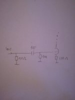
So add a capacitor between output of the DAC and the grid. 1uf and 1M from grid to gnd. You can leave the 100 ohm between DAC output and gnd
That will definitely work, unfortunately the lampizator approach ignores the fact that the DAC has balanced current outputs. Consider using a transformer as part of the I/V conversion. (Lower distortion, and less out of band noise since the transformer leakage inductance reduces it.)
Look at transformers from Lundahl or similar. Lots of options - with small I/V resistors you can use mic transformers and also get some gain ahead of the tube stage. You can also use transformers designed specifically for I/V conversion such as made by Sowter (follow their guidelines)
Look at transformers from Lundahl or similar. Lots of options - with small I/V resistors you can use mic transformers and also get some gain ahead of the tube stage. You can also use transformers designed specifically for I/V conversion such as made by Sowter (follow their guidelines)
So add a capacitor between output of the DAC and the grid. 1uf and 1M from grid to gnd. You can leave the 100 ohm between DAC output and gnd
Something like this?
Attachments
That will definitely work, unfortunately the lampizator approach ignores the fact that the DAC has balanced current outputs. Consider using a transformer as part of the I/V conversion. (Lower distortion, and less out of band noise since the transformer leakage inductance reduces it.)
Look at transformers from Lundahl or similar. Lots of options - with small I/V resistors you can use mic transformers and also get some gain ahead of the tube stage. You can also use transformers designed specifically for I/V conversion such as made by Sowter (follow their guidelines)
So what I need is a transformer that convert balanced to unbalanced-correct me if I am wrong. Unfortunately in my country I can't find dedicated transformers like Lundahl or Sowter, but I will certainly order one of this when my DAC will be in the final phase. Right now I only want to make the tube buffer work somehow, so I could make different test on the DAC.
I think that I can easily find microphone transformers, would this be a proper one?
https://www.monacor.com/en-us/monac...ignal-processing/signal-optimisation/dib-110/
Also, what is that ratio? 1:1 or 1:10? In my case which is the best?
I would like to stick with the 135ohm I/V conversion because I would like to use the DDAC design and pin 20 CSS setup for the best SQ.
In the original Doede post, there were people that connect the lampizator successfully to PCM 1794 DAC. They also used a transformer or they use other method? Something like connecting A+ with B- output....
That will definitely work, unfortunately the lampizator approach ignores the fact that the DAC has balanced current outputs.
CD300_Shanling_Burrbrown_PCM1794
It seems that it should work with PCM1794 too, without a transformer.
Don't get me wrong, I understand that this method isn't the best or very correct, but right now mine isn't working at all, and I don't understand why😡
Adding the cap and resistor suggested in a previous post should do the trick provided the chip itself is not damaged in some way.
In terms of a transformer for balanced to unbalanced conversion I would recommend something like 1:10 which is the reverse of the one you suggested - if cheap might be an interesting experiment, but I suspect it is not a particularly good transformer.
I would reduce the 100 ohm dac resistor values to keep from overloading the tube stage. You will need to experiment based on the transformer you end up with, and how much signal you need at the output.
I've used resistors in the range 5 ohms to 51 ohms or so but I was running 1794A in mono mode with twice the current of a single stereo channel. (I summed the currents since the dacs look like independent current sources.)
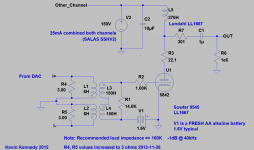
Don't be afraid to experiment, my suggestions are very general and based on a 1:5 Sowter with 2 x the default dac output current. I used < 5 ohms per output phase. Output amp was choke loaded 417A/5842. (Gave the whole thing to a friend a few years ago, he's still using it.)
See attachment, results depend heavily on the transformer. I'd recommend something good if you have a significant investment in this dac project.
In terms of a transformer for balanced to unbalanced conversion I would recommend something like 1:10 which is the reverse of the one you suggested - if cheap might be an interesting experiment, but I suspect it is not a particularly good transformer.
I would reduce the 100 ohm dac resistor values to keep from overloading the tube stage. You will need to experiment based on the transformer you end up with, and how much signal you need at the output.
I've used resistors in the range 5 ohms to 51 ohms or so but I was running 1794A in mono mode with twice the current of a single stereo channel. (I summed the currents since the dacs look like independent current sources.)
Don't be afraid to experiment, my suggestions are very general and based on a 1:5 Sowter with 2 x the default dac output current. I used < 5 ohms per output phase. Output amp was choke loaded 417A/5842. (Gave the whole thing to a friend a few years ago, he's still using it.)
See attachment, results depend heavily on the transformer. I'd recommend something good if you have a significant investment in this dac project.
Attachments
I am also using PCM 1794 in mono mode. When you said that you summed the currents, you connect the A+ with B- ?
I looked over what is avaible on the market in my country and I didn't find any transformer that meet the requirment, so for now I will have to stay only with the tubes.
What about Broskie Cathode Follower? It seems that transform balanced outputs to unbalanced.
http://ep.yimg.com/ay/glass-ware/bcf-9-pin-pcb-user-guide-6.gif
I am also using PCM 1794 in mono mode. When you said that you summed the currents, you connect the A+ with B- ?
I looked over what is avaible on the market in my country and I didn't find any transformer that meet the requirment, so for now I will have to stay only with the tubes.
What about Broskie Cathode Follower? It seems that transform balanced outputs to unbalanced.
http://ep.yimg.com/ay/glass-ware/bcf-9-pin-pcb-user-guide-6.gif
I like this solution. The BCF is a very nice sounding circuit, changes balanced to unbalanced, and works well enough with simple resistor I/V conversion, and has nearly infinite possibilities for power supply and tube options.
I like this solution. The BCF is a very nice sounding circuit, changes balanced to unbalanced, and works well enough with simple resistor I/V conversion, and has nearly infinite possibilities for power supply and tube options.
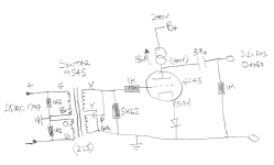
User clivem had used the BCF circuit with his PCM1794 DAC, then mouved to another aproach using transformers and tubes like in the attachement.
What are the advantages/disadvantages for using a transformer vs BCF?
Attachments
I am not sure why clivem switched from the BCF circuit to transformers, but for your decision it depends on your preferences.
There will be sonic differences, but it depends on the type of sound you prefer and what you're trying to accomplish in terms of design.
THe BCF circuit is very tailorable to your sonic preferences, and can use any number of octal or noval tube types (depending on which circuit board you order).
Cost wise, the Sowter 9545 (obsolete, I think, replaced by the 1465) is expensive at GBP £105, and you'd still need a tube preamp circuit like the one you've drawn and a power supply.
The BCF circuit can be built under US $100 plus a power supply and sounds pretty nice using passive I/V from the PCM1794.
Stupid question, why did you soldered all tantalum with + that ground?
What tantalums?
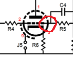
baldrick: one thing I don' understand: on the BCF schematics, the lower tube grid has two connections. The one that I circled is the same as the one from pin nr. 2, and is connected like this to have a more clearly schematic?
Attachments
Last edited:
Stupid question, why did you soldered all tantalum with + that ground?
It is the standard EU symbol for a polarized capacitor, not necessarily a tantalum, but as you noted it is drawn wrong way around..(+ to GND) 😀
Schematic Symbols - The Essential Symbols You Should Know
- Status
- Not open for further replies.
- Home
- Source & Line
- Digital Line Level
- PCM 1794 with tube output problem