Hi all,
I have built both a DIGI125 and a SC480. The SC480 is Silicion Chip's update to the original ETI480. I believe Graham Dicker is the designer of the Digi125 and still sells them from his website. I don't think he designed the original ETI480 or the SC480.
My SC480 has been built pretty much standard according to the kit. I did built my own power supply though.
The DIGI125 in its standard form has a few bits missing IMHO. After modifying the DIGI125 from information gained in a few threads in this forum, it sounds a fair bit better than the SC480 (IMHO).
The two mods that it think made the biggest difference was adding an extra bias diode and addding a bootstrap to the output.
Thanks
Greg
Is this the amp you are looking for?
http://www.dse.co.nz/cgi-bin/dse.storefront/40b68904042722d2273fc0a87f9906b1/Product/View/K3442
http://www.dse.co.nz/cgi-bin/dse.storefront/40b68904042722d2273fc0a87f9906b1/Product/View/K3442
Greg Erskine The DIGI125 in its standard form has a few bits missing IMHO. After modifying the DIGI125 from information gained in a few threads in this forum, it sounds a fair bit better than the SC480 (IMHO).
Let us know the total changes u hv done to Digi 125. Ur comments r interesting & prompts us to make Digi 125. It is better if u give schematics of modified one.
Hi, I'm Steve and I am from Romania.
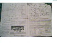
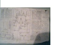
I started building a module of the ETI480 from scratch, no such thing as a kit for the ETI480 here in Romania, and I encountered a little problem: I downloaded everything there was to know from Paul Cambie's site (re: ETI480, schematics etc.) and I found a mismatch on some resistor values between the pages of the same author
If you will be so kind to look at Fig. 14, ETI Parts List, in my attached file, you will see that R4 is 2K7 and R5 is 2K1, but in the circuit diagram, found on first page, we can all see that R4 is 5K6 and R5 is 2K7 Am I seeing wrong, somebody please tell me...
I am also wanting to use MJ15003 and MJ15004 for the output stage and BD237 and BD238.
Has anywone used them and what are your remarks on the difference between them and the 2N3055/2N2955, BD139/BD140.
Please excuse my english if made any mistakes.
Thanks, Steve
I was wondering about the resistors as well...
P.S: I once had a very bad experience with Graham Dicker; he is a very bad seller in eBay!

Hi palesha,
I followed the advice in this thread.
Greening a classic
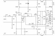
I bought some mk7 boards from RCS, they're not pretty to look at, but did the job. The actual PCB layout is far from perfect. I've tried most of the things mentioned in the above thread but didn't invert the circuit because of the PCB I bought. The PCB has enough room add the additional components. Mine looks close the the schematic shown in "Latest Schematics! Long Post!" except I used 3 diodes for biasing.
I started with the Toshiba output devices, so I can't comment if they are better than standard. I found the advice in this thread to be quite accurate and most of the modifications proved beneficial IMHO.
An additional thing I tried was adding a zobel to the output. I found it made no obvious difference to the sonics so I left it in. My test power supply is a single 160VA 18-0-18 Toriod with two bridges and 4 x 4700uF filter caps.
BTW: An interesting fact emerged during my experiments with the DIGI125. The results of each change was exactly as I expected. So either, the advice was very good or I convinced myself that's things got better. 🙂
I followed the advice in this thread.
Greening a classic
I bought some mk7 boards from RCS, they're not pretty to look at, but did the job. The actual PCB layout is far from perfect. I've tried most of the things mentioned in the above thread but didn't invert the circuit because of the PCB I bought. The PCB has enough room add the additional components. Mine looks close the the schematic shown in "Latest Schematics! Long Post!" except I used 3 diodes for biasing.
I started with the Toshiba output devices, so I can't comment if they are better than standard. I found the advice in this thread to be quite accurate and most of the modifications proved beneficial IMHO.
An additional thing I tried was adding a zobel to the output. I found it made no obvious difference to the sonics so I left it in. My test power supply is a single 160VA 18-0-18 Toriod with two bridges and 4 x 4700uF filter caps.
BTW: An interesting fact emerged during my experiments with the DIGI125. The results of each change was exactly as I expected. So either, the advice was very good or I convinced myself that's things got better. 🙂
toshibas and eti
any one looked at using the toshiba transistors in the eti 480 one of the mod's for for digi125 is the use of the toshiba tranisitors.???😕
any one looked at using the toshiba transistors in the eti 480 one of the mod's for for digi125 is the use of the toshiba tranisitors.???😕
Hi,
Any advice is appreciated.
I have made 3 Digi 125 amps now and they all seem to have
lower output than my stereo 25W /25W amplifier.
I have used all the combinations of transistors mentioned ,
i.e 2sc5200 ... MJ802.
The power supply is 4A 28-0-28 AC.
All the parts are as per the schematic.
Though I did notice differences between the parts list and the schematic. R3 & R4 are shown as 47K in parts but 4K7 in the schem.Q4 is shown as BC556 in parts but BC557 in schem.
The only thing I can think of is that my DVD player is not putting out enough input for the input of the Digi.
The output of the digi is dependent on the input voltage as there is no volume control .
What about if I make a pre amplifier using a 741?
I have also made the eti 272 audio level detector and this also shows me that the digi will only just light the led that is 50W on the peaks. I did calibrate this as per instructions.
Oh I also have made my own update to the PCB which is about twice the size of the original, which helps a lot especially with modifications and tired old eyes.
Steve.
- Status
- Not open for further replies.
- Home
- Amplifiers
- Solid State
- PCB pattern for 100W Amp