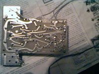
PCB Pattern for 100W Amp
Vivek,
The management of Elektor has changed. A face-lifted version appeared for some months and now is not seen any more. As for EFY, you are dead right. I think they see their clientele in MBA graduates.
I was just trying to build the ETI 100W version. But members in this forum, including Mahendra Palesha, have suggested that 2SC types produce as much Wattage without having to use double pair in the output. Now I am looking for these output devices.
Thanks.
Hi Shashidhar,
The PCB for the ETI 480 is given in one of the pdf documents, but the silkscreen of the components is not very clear, especially for the output transistors. Could you help me out?
Palesha,
There was another thread called 100 W amp (I think) where most people said that the sound would not be so good due to the protection circuit. I think you can really tell after building it.
Vivek
PCB Pattern for 100W Amp
Vivek,
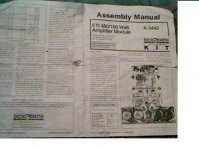
Which PDF are you referring to? I have the complete article of ETI480 project from the journal itself. I can send you a copy (snail-mail) if you tell me where to mail it to.
The original pcb pattern and all other diagrams is available in the file I have attached below:
Vivek,
Which PDF are you referring to? I have the complete article of ETI480 project from the journal itself. I can send you a copy (snail-mail) if you tell me where to mail it to.
The original pcb pattern and all other diagrams is available in the file I have attached below:
Attachments
Shashidhar,
I have this file. I wanted the figure that shows where each component is to be soldered. You see, the PCB layout in the document you have attached does not have this.
If you have a scanned copy of the article, could you mail it to me at mayday11in@yahoo.com. Thanks.
Vivek
I have this file. I wanted the figure that shows where each component is to be soldered. You see, the PCB layout in the document you have attached does not have this.
If you have a scanned copy of the article, could you mail it to me at mayday11in@yahoo.com. Thanks.
Vivek
I am going out of station today. I will give u details after i come back on Tuesday. I have made one pcb with japanese devices. So don't waste ur time for the same mechanical thing. Till the time decide that u want to make ETI 480 or not? I will gice postscript file by which u can easily make pcb. Till the time excuse me,
Mahendra Palesha
Mahendra Palesha
Hi Palesha, Shashidhar,
Which PCB design software do you use and does it have autorouter and is it freeware?
Vivek
Which PCB design software do you use and does it have autorouter and is it freeware?
Vivek
Dear Vivek,
For the circuits available on the net, I use Pagemaker. U will & everyone else will be surprised. I have written few scrips for it & customised it as per my liking. It consumes more time than dedicated softwares but it is very easy to work & i can design it the way i want to without any kind of limitations.
Mahendra Palesha
Hi Palesha,
That is very interesting. I suppose you have done some coding on your own. But can it do PCB layouts too?
Vivek
That is very interesting. I suppose you have done some coding on your own. But can it do PCB layouts too?
Vivek
I have almost designed everykind of pcb from RF to AF. I am using it from last 7 years. I am happy with Pagemaker. I have made component library of my own. I am able to make masking artwork with my scripts. If u want to know anything more let me know.
Mahendra Palesha
Mahendra Palesha
Hi Palesha,
I suppose you have to draw out all the components yourself. But how do you draw the PCB layout?
Vivek
I suppose you have to draw out all the components yourself. But how do you draw the PCB layout?
Vivek
PCB Pattern for 100W Amp
Palesha, Vivek,
I have tried Protel off and on for some years now. The version I have downloaded does not have auto place but autorouter yes. Not convincing though.
Palesha,
PageMaker for PCB? Haven't heard anything like that before. Please could you explain yourself to me a little more? Thanks for the PS file.
Hi Palesha, Shashidhar,
If you have the PS file for the ETI 480 could you pass it on to me? And does any one have the component layout for the ETI 480 amp? Thanks in advance.
Vivek
If you have the PS file for the ETI 480 could you pass it on to me? And does any one have the component layout for the ETI 480 amp? Thanks in advance.
Vivek
U have to do layout homework first. Then just palce the components from the library. Connect the components with the square tool. If u have got pagemaker then i can send u one file of the pcb. I make pcb with 6 layers information. U will come to know everything once u open my file in Pagemaker.
Mahendra Palesha
Mahendra Palesha
Hi Palesha,
I have Pagemaker. Send me the file you mentioned and I'll check it out. But now that I have Eagle things are so easy. Why don't you try it too?
Cheers,
Vivek
I have Pagemaker. Send me the file you mentioned and I'll check it out. But now that I have Eagle things are so easy. Why don't you try it too?
Cheers,
Vivek
eti480
Hi, I'm Steve and I am from Romania.
I started building a module of the ETI480 from scratch, no such thing as a kit for the ETI480 here in Romania, and I encountered a little problem: I downloaded everything there was to know from Paul Cambie's site (re: ETI480, schematics etc.) and I found a mismatch on some resistor values between the pages of the same author
If you will be so kind to look at Fig. 14, ETI Parts List, in my attached file, you will see that R4 is 2K7 and R5 is 2K1, but in the circuit diagram, found on first page, we can all see that R4 is 5K6 and R5 is 2K7 😕 Am I seeing wrong, somebody please tell me...
I am also wanting to use MJ15003 and MJ15004 for the output stage and BD237 and BD238.
Has anywone used them and what are your remarks on the difference between them and the 2N3055/2N2955, BD139/BD140.
Please excuse my english if made any mistakes.
Thanks, Steve
Attachments
I have used these amps. I have 3 of them (tweeked)here and they are very good they and can be tweeked to 200-220w by changing the out put to 2x mj15003 and mj15004 the bd139 and bd140 to mje340 and mje350 ,r6 on the zener from 3.3k to 4.7k and change the r15 and r16 between the drive transistors from 33ohm 1w to 33ohm 5w and use 50v rails the resistors on the output transistors get hot to but I havnt changed them I have pcb pics (not layouts on comp) schematics and pics of amp if you need them just email me .I used 2 p2 comp heatsinks to keep it cool to workes very good .If my freinds cant kill it it cant be killed .it runs on full all day every day
r4 is 5.6k and r5 is 2.7k in the 100w version and on last post you can go to 6.2k on r6 to use 60v rails but not 1v more I think it was around 250-260w and a **** load of heat 

- Status
- Not open for further replies.
- Home
- Amplifiers
- Solid State
- PCB pattern for 100W Amp