😎
I think I'm on the right track. I updated the board a bit because I have a doubt that they designed it badly and then revised/fixed it later. I did the zones and there are no connection errors, but the fact remains that the zone has a different color from the tracks and maybe that's also how it should appear.

I think I'm on the right track. I updated the board a bit because I have a doubt that they designed it badly and then revised/fixed it later. I did the zones and there are no connection errors, but the fact remains that the zone has a different color from the tracks and maybe that's also how it should appear.

I'm still not entirely clear on why different cards trace in different ways. This is exactly how Rogers .../FL6 has been defining traces for many years. Perhaps it's my limitation in this regard and I need to study better how the signal travels along the path.

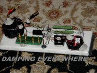
I had to stick with what I had available, 1/2" Corian that could be cut to size. Once I securely mounted a sizable ground wire, the other connections came easily. I am against ty-wraps and found a good silicone adhesive that held anything in place that needed to stay put. epoxy was used for a few spots, and finally, strong, quality , spring loaded connectors were used for the drivers. To make taking the crossover out of the cabinet easier, I used banana connectors inside of the cabinet.
Attachments
the big question:
I've been wondering for 4/5 days if the zones in a crossover can lack the signal transit compared to the scheme that defines the signal that must first pass through e.g. C1, then L2, then R1 r after R3. instead maybe these are all together in one zone, they group together and then move on. this thing drives me crazy.
I've been wondering for 4/5 days if the zones in a crossover can lack the signal transit compared to the scheme that defines the signal that must first pass through e.g. C1, then L2, then R1 r after R3. instead maybe these are all together in one zone, they group together and then move on. this thing drives me crazy.
Corian leftovers from a countertop maker. Easy to work with using a table saw, drill or sander. Solid not flimsy like what I see or have worked with before. "Famous" speaker maker who charges zillions for his work, used a flimsy, and yes, I mean flimsy, thin breadboard to make a crossover on. If you can't start with a decent base, you already don't have my respect, no matter how much the other components cost.
No? If a cap input and an inductor input both need to be connected to the positive input, all three can be "zoned" together, no need for a trace to go from the positive to the inductor input then the cap input. Is this what your referring to?
yes.
but let's suppose that the cap goes first, then the inductance and then the resistor.
in this case if the resistors are on the same, doesn't anything change?
but let's suppose that the cap goes first, then the inductance and then the resistor.
in this case if the resistors are on the same, doesn't anything change?
Electrical signals travel near the speed of light. Splitting hairs as to how fast that the component responds to them is a moot point.
I think I understand.
But here is a practical example of my perplexity. The three points of the 3 components in the same area place the directionality differently.

But here is a practical example of my perplexity. The three points of the 3 components in the same area place the directionality differently.
May be B&W can help you. Four of the circled parts are connected among themselves in the blue part of the pcb.

Yes, but all four connections can be a big zone like it's shown on the crossover layout.

- Home
- Loudspeakers
- Multi-Way
- PCB or not PCB, this is a problem