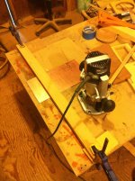
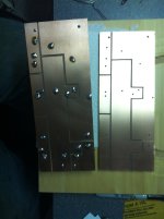
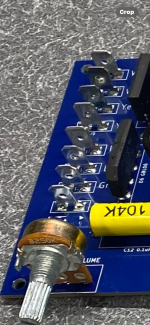
Curious to how you connect speaker wiring to this PCB with those small holes. I use spades with 2 pins on a PCB for all driver wiring connections in my speakers.I make PCBs for the crossovers of all speakers that will be kept by myself or others. Definitely everything that goes into production. It greatly reduces the chance of a wiring error and makes the finished speakers look far more professional.
PCB is the way to go if you're making more the 2 of each.
Holes should be big enough to accept a polarized spade connector
Holes should be big enough to accept a polarized spade connector
LOL, the next version had larger holes for the input and the woofer, to accept 14AWG wire, which is direct soldered. The first 10 boards were a bit of a nuisance and required a J hook in those four holes. Like this:

18AWG is fine for the mid and tweeter.
With everything, there's always some iteration towards perfection.
18AWG is fine for the mid and tweeter.
With everything, there's always some iteration towards perfection.
Last edited:
I had another idea to make it at home, maybe I'll install kiCad just to see how it looks, then I'll make it in the garage.
🙂
🙂
Very different 😉 Why make it difficult when you can have good quality nice looking boards by JLCPCB?
Chances are that raw PCB material is more expensive in your county.
I had very large boards made for non electronic use (yes they had some trouble with that) recently and they were affordable and very good looking.
Chances are that raw PCB material is more expensive in your county.
I had very large boards made for non electronic use (yes they had some trouble with that) recently and they were affordable and very good looking.
Last edited:
All nice and such but besides costing more time and effort to reach holy DIY status how are you going to protect tracks against corrosion?
How to make exact pads for faston 6.3mm or screw connectors?
Not wanting to drag down anything but there is a reason stuff is either hardwired or mounted on a CAD PCB. Coated, plated through, part numbers, text, optimal part placement with right footprints etc. Your method seems to be inbetween but not “best of both worlds” 😀
I was a stubborn type and refused to let software decide how to work. Till the day the guy that etched my boards refused my hand drawn films. Meanwhile I draw like I did manually but with the bonus my boards can be made fast and affordable.
Last edited:
What are the pros and cons of the method?
One con is the screw connector type that has 2 possible errors per contact. But that is a choice as wires can be soldered.
One con is the screw connector type that has 2 possible errors per contact. But that is a choice as wires can be soldered.
Looks good but what are the technical pros and cons?
Are the parts glued with silicone or similar to avoid resonance/mechanical noise?
Are the parts glued with silicone or similar to avoid resonance/mechanical noise?
Pros are simply looks. It's not going to"sound" any better.
Cons, it has to look good and it's more work because of that.
If it's not going to be seen, then I'll just glue/attach components to piece of hard board and point to point wire it up.
I personally like trying new things, so exploring diff ways of assembling a crossover is another way of being creative.
I use a product called GOOP. It's similar to silicone, but thicker/sturdier and zip ties where needed.
How to make exact pads for faston 6.3mm or screw connectors?
Not wanting to drag down anything but there is a reason stuff is either hardwired or mounted on a CAD PCB. Coated, plated through, part numbers, text, optimal part placement with right footprints etc. Your method seems to be inbetween but not “best of both worlds” 😀
I was a stubborn type and refused to let software decide how to work. Till the day the guy that etched my boards refused my hand drawn films. Meanwhile I draw like I did manually but with the bonus my boards can be made fast and affordable.
Don't worry, you won't ruin anything, I understand that I will encounter difficulties, but I have to get there in small steps 🙂
I was thinking of using faston 4.8 connectors soldered directly on the track, but also of avoiding accessories and soldering the wires directly on the tracks. I have already prepared the printed circuit board with exact positions and the various numbers C1...L1/2 R1/2 this is very small and easy. the base is about 10*8cm maybe less.
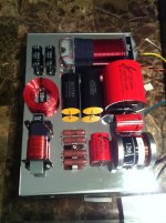
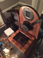
I have done the exposed crossover, looks great. I stepped it up and did it under glass, too.
View attachment 1438166
View attachment 1438167
your creation is interesting. free mid-woofer and reflex woofer below?
- Home
- Loudspeakers
- Multi-Way
- PCB or not PCB, this is a problem

