Hello guys
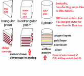
some idea of cylindrical or whatever VERTICAL shaped amplifiers... Can be used later in horizontal manner.
Best thing is the airflow that never stops and non solderability or less solder.
Second best is the chance to use various plated wires, nickel plated(nice at low temperatures), gold plated, silver plated rings and so on. brass, iron, steel, they all add and remove something, manipulating with the impedance curve.
Third best is the rings(layers) can be shaped, cuz corners of different shape matter a lot.
Last is that its FUN, from the 70s ( TUBE ERA) and its matrix also.
SMD can be used.
I dont see any cons from this kind of a PCB... nothing is required to build countless layers. No machines are required. Minimal waste is created.
Has anyone tried that approach ? Induction and capacitance can be made out of wires...lich wires, anything can be used to make capacitor between layers(miller caps and so on).
I have never tried this, but i am planning to.
So guys, Is there any cons ?
Attachments

Last edited:
Or just use simply ladders on top of each other and if successful, a race of using less fancy stuff can be started. Cuz to me it seems we are listening to metals ------theyr bandwidth that they provide within different factors, like current, voltage, resistivity, air, temp, shape, coupling and gravity lol 😀
Differences in inches of metals is measurable in a laboratory, not in an amplifier at audio frequencies. Physics works the same for all of us. Do not confuse microwave circuits with audio. At high frequencies, yes we do use the traces and wires as components. I remember the pirate HBO antennas I built had a couple transformers as part of the board. Even a trace worked like a transmission line. Some even make caps on the board. But we were talking 2 Gig, not 20K. You should evaluate where your "Cuz to me" comes from. Cuz to me, not from engineering.
It is fun to look at alternative packaging layout. There is no rule we have to have a horizontal box, so have fun. Fabrication might be difficult. Have you thought about "flexie-circuits"
It is fun to look at alternative packaging layout. There is no rule we have to have a horizontal box, so have fun. Fabrication might be difficult. Have you thought about "flexie-circuits"
I'm sorry but I'm having trouble understanding the relevance of anything you've said to anything to do with audio electronics, it seems completely out there and divorced from reality of low frequency analog electronic design. For instance the shape of an amplifier is irrelevant to anything but thermal convection, the surface plating of a conductor has no relevance at audio frequency, and its not clear what you are saying regarding PCBs at all.Hello guys
some idea of cylindrical or whatever VERTICAL shaped amplifiers... Can be used later in horizontal manner.
Perhaps you can start again, making individual points separately and clearly (rather than a word cloud !!) - for instance yes, SMD can be used, but how is that unique?
Differences in inches of metals is measurable in a laboratory, not in an amplifier at audio frequencies.
It depends on the measuring equipment, what kind of a unit that is measured is also important. Its questionable. I think audio benefits more from bandwidth.
Bandwidth vs speed, which is of more importance ?....
RIP:
“Don't fear the man who knows 1,000 techniques. But fear the man that has practiced one technique 1,000 times.” :Bruce Lee
I am saying that we could drop the idea of a pcb, cuz there is no chance to manipulate with length, thickness, grounding points, materials in live action.
All PCBs are doing is setting up the limit, they are only good for mass-production.
Even stiffness matters, stiffness of the material and the circuit overall.
All PCBs are doing is setting up the limit, they are only good for mass-production.
Even stiffness matters, stiffness of the material and the circuit overall.
But guys, i think its too late, its either gonna be Meta vers or Nukes, i wish nukes... cuz something is out there, it cant be killed cuz noone knows how... Hes the culprit of disbalance of this world. When he gets in ur head..... its another disbalance.
i believe that taking down the earth will work, cuz mostly, he lives in flesh.
i believe that taking down the earth will work, cuz mostly, he lives in flesh.

Lol, but i think its worth to try this method, nap circuits should definitely benefit from it. Maybe it is the route naim should have been following from the start. I cant comment on bandwidth benefits but maybe it is an upgrade if one knows how to lay out components from the bottom to the top. You cant trust even a company nowadays.
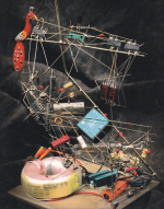
There are far more attractive examples out there: https://www.google.com/search?q=fre...&biw=360&client=ms-android-lge-rev1&prmd=sinv
....but the picture Jan posted more closely matched my mental image.
....but the picture Jan posted more closely matched my mental image.
😍There are far more attractive examples out there: https://www.google.com/search?q=fre...&biw=360&client=ms-android-lge-rev1&prmd=sinv
....but the picture Jan posted more closely matched my mental image.
@ Rensli
I'm also the type to let my imagination wander to change perspective and see differently but for that you have to start from the ground, you can't build a house starting with the roof, you have to start with the base, the fundamentals, and when you master them at 200%, then you can let your imagination express itself to look for other ways.
I'm also the type to let my imagination wander to change perspective and see differently but for that you have to start from the ground, you can't build a house starting with the roof, you have to start with the base, the fundamentals, and when you master them at 200%, then you can let your imagination express itself to look for other ways.
😀
I dont know, but we could bypass soldering and to me solder is a kind of a bottelneck in audio. Some solder will do fine.
You know, if you solder a transistor into a PCB, that transistor must drive that solder joint also. If that solderjoint is heavy in mass or made of multiple metals than wtf... 😀 Finding a solder that suits that particular transistor and driving conditions is not a dumb idea, imo its a perfection. Simple schematics done wisely tend to be godlike
Last edited:
There is something with the platings, resistor leg platings, transistor 3 leg platings, they all contribute heavily into sound, care should be taken when handling..
......polish the legs of these components and reveal bare copper or some other alloy.
As huggy said, we have no fundamentals... and noone knows anything for sure and its fun either way.
......polish the legs of these components and reveal bare copper or some other alloy.
As huggy said, we have no fundamentals... and noone knows anything for sure and its fun either way.
Basic stuff, like pcb layout track width, how wide and why ? lol 😀
Why feedback pcb track width should be less than 0.9mm ?
Most basic stuff....
I think its much easier to try it without PCB design, noone has a real-time simulator that can predict naim 😛
Why feedback pcb track width should be less than 0.9mm ?
Most basic stuff....
I think its much easier to try it without PCB design, noone has a real-time simulator that can predict naim 😛
You should build an example of your dream construction method in the form of an audio power amplifier - any linear type of say 10W, 8R minimum output, since this is the general topic here in the solid state forum. Then post some pics and the results of listening tests where it is compared with a typical commercial amplifier of similar power, both driven at the same maximum safe output level, to a loudspeaker load.
I'm sure people will be more interested in a real, working model than the often flaky construction ideas and inspirations that most of us have at some time. You may hear an improvement over a commercial PCB design but lets at least see what criteria you have for comparing whatever models you have in mind.
I'm sure people will be more interested in a real, working model than the often flaky construction ideas and inspirations that most of us have at some time. You may hear an improvement over a commercial PCB design but lets at least see what criteria you have for comparing whatever models you have in mind.
Last edited:
Minecraft mode can be entered, making a motherboard, allowing us to change CSS, VAS, FEEDBACK compartments and so on to find the secret recipe.
I will try something in the future, if there is such thing as future....
I will try something in the future, if there is such thing as future....
Attachments

Last edited:
Positioning of an amplifier in the room. If you think you breathing air ? Or is it something else ?
Can naim circuit and positioning benefit from that kind of perspective ?
Is AC even real ? How an amp comes microphonic, so that even a slightest touch of the amp PCB board can be heard from a speaker ?
Can naim circuit and positioning benefit from that kind of perspective ?
Is AC even real ? How an amp comes microphonic, so that even a slightest touch of the amp PCB board can be heard from a speaker ?
- Home
- Amplifiers
- Solid State
- PCB-less amplifier design notes