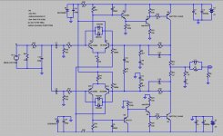
Hello to everyone. Does anybody have a pcb layout (drawing) for Musical Fidelity A1 amplifier? I mean the old and classic version from this link: View image: schema 2 Thanks in advance.
Last edited:
In this case it s adequate to get a nice and typical tubbish sound, this was apparently the goal of the designers.
The schematic has an error, one lectrolytic cap is wrongly polarized - see if you can find which.
Plenty of ebay sellers offering what claim to be A1 boards.
Given the real thing can be had for a little over £200 buying one and recapping it would seem to be as sensible a solution as any.
Given the real thing can be had for a little over £200 buying one and recapping it would seem to be as sensible a solution as any.
My class A
Guys, if you look carefully, it does not really matter. DC voltage at the bases is very low and if you simulate the thing, you will see that the bottom base is more positive than the top one (some 20mV difference or so).
I did my own class "A" design, based on the same principle, but having much lower distortion, some time ago - see my links >HERE<
The one I've built is an excellent one - extremely transparent, ultra-low distortion, 2-nd harmonic is dominant (although, it's extremely low), etc.
See the live measurements, listening impressions - everything is there. I can recommend it with no hesitation.
Cheers,
Valery
Attachments
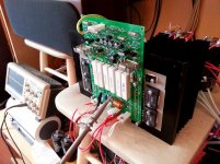
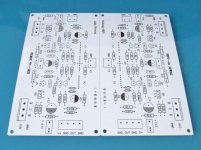
did this one in 2011
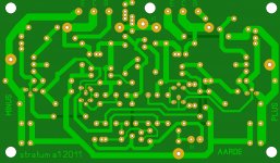
I have built many many own versions of the A1, A100 and A1000 since 1991 till 2012. Mostly on veroboard but this one I redesigned to make myself some pcb's.
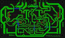
You see the pcb from above with x-ray. You have to sort out which component has to sit where.
I have built many many own versions of the A1, A100 and A1000 since 1991 till 2012. Mostly on veroboard but this one I redesigned to make myself some pcb's.
You see the pcb from above with x-ray. You have to sort out which component has to sit where.
Attachments
Last edited:
as said
As said I made tens of copies. I'm probably the person who tested the most variants of this circuit in the world (is it? I'd like to hear others):
- several layouts
- pcb and hard wired
- own design and copies from china
- a1 and a1000 (parallell versions)
- fancy components and cheap versions (as is the original)
- small power supply, heavy power supply
- big cooling and moderate cooling
I have to pay my respect to MF for making so musical a design with a minimum amount of components and money. It is quite hard to accomplish this task yourself! I needed 10 years to come to this conclusion ....
Yes, it is way better to buy dead piece of original one and remake that one. But: the original becomes too hot, so thinking creatively about cooling the stuff will pay off.
like to see
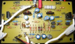
No thank needed mr Georgescooo (well, you can see my name on the pcb ..). I would appreciate your findings when building your amp. Even after all these years I'm not totally sure what exactly determines the sound of this amp. I'm quite sure the small caps (22pf, 680pf, 333pf) do make a difference soundwise (the values of course, but also the material and brand used).
I have experimented a lot with the 1uf at the entrance. Standard this is a no-name (Jamicon, that is) electrolytic. We highenders are prone to putting in some fancy stuff here, like polyester of polypropylene. I have used all kinds of caps here, but for some reason I always return to the cheapest electrolytics that help to give this amp some bloom and easy going sound. Sure you can use known brands here like Nichicon, Philips or Panasonic (still being electrolytics for 50 cents a piece max).
By the way: I once had an original A1000 on loan from a friend. As you know this is exactly the same circuit (including the electrolytics at the entrance!). In my situation this amp could not match my original (but recapped) A1 and not my diy-A1000.
Well, in the end I gave up trying to understand this circuit. That's why I like to hear findings of other diy-ers, preferably from own experience in building and listening (no common wisdom that is repeated from forums 🙂 ).
Thank you very much Mr. rmgvs for the pcb layout and all the other informations.
No thank needed mr Georgescooo (well, you can see my name on the pcb ..). I would appreciate your findings when building your amp. Even after all these years I'm not totally sure what exactly determines the sound of this amp. I'm quite sure the small caps (22pf, 680pf, 333pf) do make a difference soundwise (the values of course, but also the material and brand used).
I have experimented a lot with the 1uf at the entrance. Standard this is a no-name (Jamicon, that is) electrolytic. We highenders are prone to putting in some fancy stuff here, like polyester of polypropylene. I have used all kinds of caps here, but for some reason I always return to the cheapest electrolytics that help to give this amp some bloom and easy going sound. Sure you can use known brands here like Nichicon, Philips or Panasonic (still being electrolytics for 50 cents a piece max).
By the way: I once had an original A1000 on loan from a friend. As you know this is exactly the same circuit (including the electrolytics at the entrance!). In my situation this amp could not match my original (but recapped) A1 and not my diy-A1000.
Well, in the end I gave up trying to understand this circuit. That's why I like to hear findings of other diy-ers, preferably from own experience in building and listening (no common wisdom that is repeated from forums 🙂 ).
I need to enlarge the R28 to 330R inordr to get the right Vbe of MJ2955,and let the temperlature down to normal. Otherwise I had burned three MJ2955。
Muscal Fidelity A1 Clone
I bought some clone PCB's from an eBay seller and I took time to simulate the A1 amplifier with the parts I am going to try out. I have the parts on hand and I am ready to stuff the boards as per the schematic from my LT Spice simulation. The simulation seems to check out pretty good.
Is there any conflicting advice I need or do you think I should proceed as per the simulation? I guess I'm looking for a sanity check. ???
Attachments
- Home
- Amplifiers
- Solid State
- PCB for Musical Fidelity A1 amplifier