Attachments
Hi Kristijan,
What is that pre-amplifier on your site? I have never heard of a Pass Sigma 6 pre-amp before. It even has Pass Labs printed on the transformer and back but it looks like a chassi from something else as the fixing holes are a bit off and at least the balanced inputs are unused.
http://web.vip.hr/pcb-design.vip/pic-18.jpg
http://web.vip.hr/pcb-design.vip/pic-28.jpg
http://web.vip.hr/pcb-design.vip/c-000015.jpg
/UrSV
The preamplifier is Balanced Zen Line Stage and it is installed in well modified enclousure of Technics preamplifier SU-C 1000 mark2.
Balanced outputs are not in use because it is still under construction (input/output selector without tape monitor switches).
Sigma 6 is printed because it have 6 inputs.
Sony minidisc is also well facelifted for more audiophile look.
Balanced outputs are not in use because it is still under construction (input/output selector without tape monitor switches).
Sigma 6 is printed because it have 6 inputs.
Sony minidisc is also well facelifted for more audiophile look.
Kristijan: On your web site link, you have a circuit diagram of Aleph 5. Correct me if I'm wrong but shouldn't the resistors at the source of the IRF244 transistors be tied together?
I believe the circuit is correct. Look at the Aleph 3 service manual for a schematic without the X3, and the Aleph 3 has two output devices in parallel, and are setup the same way that kristijan did his.
--
Brian
gte619j@prism.gatech.edu
--
Brian
gte619j@prism.gatech.edu
Brian and Kristijan are absolutely correct.
Each FET plus it's source resistor should be independent. The sensing circuit only need to look at one of these because they are perfectly balanced.
cheers, mark
Each FET plus it's source resistor should be independent. The sensing circuit only need to look at one of these because they are perfectly balanced.
cheers, mark
Brian,
As you know, I'm planning on building Aleph 2. The circuit diagram shown on Kristijan's web link caught my attention because I want to compare the differences between Aleph 2 and Aleph 5.
I've check out the circuit diagram of Aleph 5 on the Pass Labs web site and it sure looks very similar to Aleph 2, especially at the outputs stage. If what was shown on Kristijan's web link is correct, does it mean that the resistors at the source of the output transistors for Aleph 2 should NOT be tied together either? I wanted to know because I'm going to be building the Aleph 2 in the near future.
There are a couple of difference for Aleph5 that I can see. Example, C7, C10 are connected differently. There are four 0.47 ohms at the output for Aleph 5 while there are six 1 ohm for Aleph 2. And then there are also some other different values of capacitors and resistors for Aleph 5. I'm assuming that X3 IRF244 for Aleph 5 is correct. I read that the X3 for Aleph 4 is not correct initially as reported on Mark's web site.
PCBs for ALEPH 2 amplifier will also be available on my website:
( http://web.vip.hr/pcb-design.vip ), and it will have 6 output devices with their current sources, like Mr.Pass used his original
ALEPH 2 amplifiers.
PCBs will be available after 22.IV.2002 and they use similar layout like Aleph 5 amplifier on my website, but dimensions are a little bigger and all parts are also located on one PCB.
Kristijan Kljucaric
Kristijan: When can the circuit diagram of Aleph 2 be posted on your web site? I would very much like to see the connections of the six output transistors. Thanks.
Alas, no, kristijan is again correct.hifi said:one error i see is the led/resistor shoudl be connected between the + and -
You could put the LED between the rails, but Nelson did not he placed it across the current source. Please check the original diagram 😉
cheers, mark
PS: I am not on a commission from kristijan !
Bear in mind that the output line is at ground potential when there's no signal. Thus, for all intents and purposes, the LED sees one rail's worth of voltage (assuming no signal).
Note that I chose to run the LED on my Aleph from rail-to-rail with two current-limiting resistors. Yes, I could do one with twice the value. I just liked the visual symmetry of having one resistor per rail. It bleeds both rails down equally at shutoff.
Grey
Note that I chose to run the LED on my Aleph from rail-to-rail with two current-limiting resistors. Yes, I could do one with twice the value. I just liked the visual symmetry of having one resistor per rail. It bleeds both rails down equally at shutoff.
Grey
fcel,
The circuit diagram of Aleph 2 amplifier is a little too big to be posted on this forum, but it is posted to the website http://web.vip.hr/pcb-design.hr
There you can also see the PCB component layout.
Kristijan Kljucaric
The circuit diagram of Aleph 2 amplifier is a little too big to be posted on this forum, but it is posted to the website http://web.vip.hr/pcb-design.hr
There you can also see the PCB component layout.
Kristijan Kljucaric
Picture of circuit:
http://web.vip.hr/pcb-design.vip/aleph-2.gif
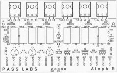
Picture of board layout:
http://web.vip.hr/pcb-design.vip/alep2-pcb.jpg
How would one keep the Aleph 2 cool, with all of the mosfets so closely spaced together? That would mean that one heatsink would dissipate 300W. That seems pretty difficult, unless you are using active cooling.
--
Brian
gte619j@prism.gatech.edu
http://web.vip.hr/pcb-design.vip/aleph-2.gif
Picture of board layout:
http://web.vip.hr/pcb-design.vip/alep2-pcb.jpg
How would one keep the Aleph 2 cool, with all of the mosfets so closely spaced together? That would mean that one heatsink would dissipate 300W. That seems pretty difficult, unless you are using active cooling.
--
Brian
gte619j@prism.gatech.edu
Brian,
Kristijan have shown -ve of C9 (220uf) connected to +ve output as per spec from the Pass Labs service manual. You have shown yours connected to the emitter of transistor MPSA18 as documented in the other thread. I have been meaning to ask you .... or anybody ...... how the circuit would operate differently from the 2 different ways of connections ..... heat wise, sound wise, speaker sensitivity wise, etc .... I'm trying to understand this circuit a lttle bit more.
Kristijan have shown -ve of C9 (220uf) connected to +ve output as per spec from the Pass Labs service manual. You have shown yours connected to the emitter of transistor MPSA18 as documented in the other thread. I have been meaning to ask you .... or anybody ...... how the circuit would operate differently from the 2 different ways of connections ..... heat wise, sound wise, speaker sensitivity wise, etc .... I'm trying to understand this circuit a lttle bit more.
As opposed to Wuffwaff's helpful comment re the amp being on (I think promitheus got that one!) I wondered this myself.promitheus said:I was always wondering why this led is connected there. Does it have any purpose ?
This is the reason that I installed a LED for each channel in my Aleph4. Not being an EE I could not guarantee Nelson hadn't used it in some subtle way as a part of the current source .... which is what I suspect promitheus was really asking, and I would like to ask as well.
Can anyone clarify this?
Otherwise I would go for Grey's approach and have just 1 LED for the power supply rails ...... I only need 1 to know the amp is on, I'm quick like that 😉
cheers, mark
- Status
- Not open for further replies.
- Home
- Amplifiers
- Pass Labs
- Pcb For Aleph 5