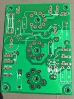
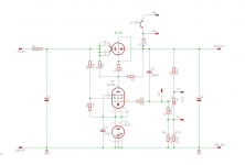
Ive just received boards for one of my projects: A regulated supply with 6S19P EF80/184 and 85A2 (or pin compatible) stabiliser.
Usefull if you need a fixed voltage
Asking €7.50 plus postage, for one board. or alternatively i'll sell you the design files for €5 so you can order the boards yourself from China. this is about €12 for 10 boards from the cheapest source.
Payment via Paypal.
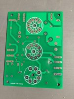
The board is pretty straightforward: size is 75x100mm and mounting holes are 3.3mm on a 65x90mm square.
The board is meant to be mounted underneath a top plate. to achieve this, the unpopulated pcb can be used to mark the drill centers. you'l need a 22-25mm drill for the tube holes.
connections are industry standard 6.3mm fastons: or alternatively you can solder directly to the board.
you can achieve a fixed or supply of 150-350V output with this PCB, current will depend on the input-output differential. The 6S19P is rated for 250V anode-cathode maximum ,100mA cathode current and 11W plate dissipation.
for different voltage requirements some of the component values will need to be changed, i can assist in calculating the required resistor values.
Usefull if you need a fixed voltage
Asking €7.50 plus postage, for one board. or alternatively i'll sell you the design files for €5 so you can order the boards yourself from China. this is about €12 for 10 boards from the cheapest source.
Payment via Paypal.
The board is pretty straightforward: size is 75x100mm and mounting holes are 3.3mm on a 65x90mm square.
The board is meant to be mounted underneath a top plate. to achieve this, the unpopulated pcb can be used to mark the drill centers. you'l need a 22-25mm drill for the tube holes.
connections are industry standard 6.3mm fastons: or alternatively you can solder directly to the board.
you can achieve a fixed or supply of 150-350V output with this PCB, current will depend on the input-output differential. The 6S19P is rated for 250V anode-cathode maximum ,100mA cathode current and 11W plate dissipation.
for different voltage requirements some of the component values will need to be changed, i can assist in calculating the required resistor values.
Attachments
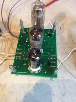
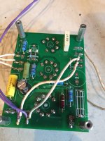
Well it works like a charm!


The TSL100/001 transformer purchased from TME is great for this as it provides 260-0-260 volt, 5V 2A in case you want to do tube rectification, 6.3V 2A which I used for the regulator and 3.15-0-3.15 volt 3A which you can use for your amplifier. sidenote: the 5V and 6.3V share a common 0V, I'm not certain wether you can pull 2A for a rectifier AND 2A for another circuit from this but for me it is of no concern. The HV is rectified with a modified rectifier... 2 diodes would have been fine but cutting off the "-" pin was just easier. This is followed by two 200uF caps. The fuse is bypassed, there is a primary fuse present though. Then the regulator receives the high voltage and filament power. Heaters for the regulator are tied to the regulated B+ in order to never go over the max cathode-filament potential. I'm going to use it to feed the "classic one" project of triodedick
The TSL100/001 transformer purchased from TME is great for this as it provides 260-0-260 volt, 5V 2A in case you want to do tube rectification, 6.3V 2A which I used for the regulator and 3.15-0-3.15 volt 3A which you can use for your amplifier. sidenote: the 5V and 6.3V share a common 0V, I'm not certain wether you can pull 2A for a rectifier AND 2A for another circuit from this but for me it is of no concern. The HV is rectified with a modified rectifier... 2 diodes would have been fine but cutting off the "-" pin was just easier. This is followed by two 200uF caps. The fuse is bypassed, there is a primary fuse present though. Then the regulator receives the high voltage and filament power. Heaters for the regulator are tied to the regulated B+ in order to never go over the max cathode-filament potential. I'm going to use it to feed the "classic one" project of triodedick
Hi Gideon,
Thanks for the Bump.
On second thoughts, the swapmeet might have been a better place to post this topic.
I only have one PCB left, I have however been working on a version two, and an unrelated version using an EL84 as the pass tube.
Gerbers and Eagle files for version 0.0 are available for free.
Cheers
- Status
- Not open for further replies.