Hi p2mine,
The first step before making any boards would be to prototype the circuit and do extensive listening.I suggest you may bulid the amp use point to point or bread boards modes at first.
I have used STK439 and STK465 dual chips for my projects in 1993 year.it is sound good,impression!
good luck
-digi")
The first step before making any boards would be to prototype the circuit and do extensive listening.I suggest you may bulid the amp use point to point or bread boards modes at first.
I have used STK439 and STK465 dual chips for my projects in 1993 year.it is sound good,impression!
good luck
-digi
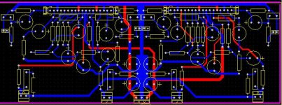
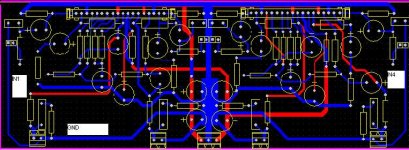
well, i've already done the point-to-point wiring.
actuallly i've already built the pcb for one STK4192 that i'm going to use as subwoofer amp.
the pcb is the one that sanyo reccomends in it's datasheet .
For me, the sound was impressing. I feel that this is the chip-amp I'm going to use.
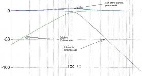
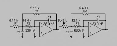
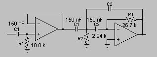
another problem for me is what filters should I use for satelites and subwoofer?
I've design for subwoofer a 80dB/decade filter using TI's filterPro utility, and for the satelites a 60dB/decade. the cutoff frequency is for sub at 120Hz, and for satelites at 150Hz.
The sum of the signals looks like this:
actuallly i've already built the pcb for one STK4192 that i'm going to use as subwoofer amp.
the pcb is the one that sanyo reccomends in it's datasheet .
For me, the sound was impressing. I feel that this is the chip-amp I'm going to use.
another problem for me is what filters should I use for satelites and subwoofer?
I've design for subwoofer a 80dB/decade filter using TI's filterPro utility, and for the satelites a 60dB/decade. the cutoff frequency is for sub at 120Hz, and for satelites at 150Hz.
The sum of the signals looks like this:
Attachments
Hey Guys
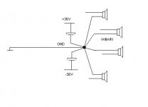
Two days ago, I finished my STK4191V after many years of being lazy. It sounded really good at listening tests, but I am wondering if the transformers I used are enough. I have used two 36 volt @ 5 Amp each,two bridges, and two 6800 uF smoothing capacitors, that gives me (+36 volt @ 5 Amp) and (-36 volt @ 5 Amp). I am driving 8 Ohm speakers, I just want to know if that is enough for this STK.
The PCB was a ready made one, bought it from Mr.Lumanauw from indonesia, the layout looks like the one stated in the datasheets. I had no oscillation problems, so that was a good enough result for me, because when I used veroboard I had notorious oscillations.
Any questions,I am here for you guys
for my stk4192 i used +-22V rails for testing.
It was clearly not enough, and now I bought a toroid with 2x25V secondary. That means around +-35V no-load.
I think this would be enough.
About your amp, i think that it's enough 2x36V .
Still, stk4191 is rated to Vcc max +-53V. It's about the power you think you need. Personaly, I think that +- 36V is enough for your amplifier.
Now, can you please draw a scatch for me?
You are saying that for every cap should i have a different trace to the ground? I'm not sure I did understad clearly.
I've drawn a scatch using paint, and now this is the layout(the condensators were replaced only by one larger condensator)
where in this layout should I put the ground for the input?
Thanks for your reply!
Regards!
Attachments
An externally hosted image should be here but it was not working when we last tested it.
This is the schetch.. I don't now why they don't display any more the pictures. Probably they don't have enough bandwith any more.....
building the PCB
lately, i was busy having school exams....
but, this is wat i've built untill now.


now one of my satelites:
two satelites, staked:
point to point wiring.....
lately, i was busy having school exams....
but, this is wat i've built untill now.
An externally hosted image should be here but it was not working when we last tested it.
An externally hosted image should be here but it was not working when we last tested it.
now one of my satelites:
An externally hosted image should be here but it was not working when we last tested it.
two satelites, staked:
An externally hosted image should be here but it was not working when we last tested it.
point to point wiring.....
An externally hosted image should be here but it was not working when we last tested it.
I've finished my amp....
now, i have aproblem. on all 4 channels I have high frequency oscilations...
I've already blew 2 tweeters...
what can be the problem??
i've used the schematics presented in sanyo's pdf..
can the cause be because of the long wires to my soundcard? (tghe wires between my computer and the soundcard are aprox 8 meters long)
should I place some 300pf in parallel with the reaction resistors? would that elimnate the problem??
- Status
- This old topic is closed. If you want to reopen this topic, contact a moderator using the "Report Post" button.
- Home
- Amplifiers
- Chip Amps
- pcb for 2xSTK4141V