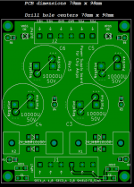
To build stereo amplifiers using LM3886 chipamp ICs, I decided I needed a small PSU board, quite a bit smaller than the "Universal Power Supply PCB" sold in the diyAudio store. This is the result. The new board is 78mm by 98mm and its mounting holes are (7.0 cm by 9.0 cm) apart. Its holes line up with the 1cm grid of holes in the chassis floor plates of Modushop / diyAudio Store chassis.
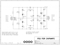
The PSU circuit schematic is shown in Figure 1, and its parts placement is shown in Figure 2, below. The PSU connects to a dual-secondary power transformer and provides dual rail (± XX volts DC) DC output voltages. The capacitors are rated for a maximum of 50V, and the diodes are rated for a maximum of 100V. This is plenty, since the chip amps themselves (LM3886) are only rated for an absolute maximum of ±42V supplies. Your power transformer's secondary voltage should be 30V AC (rms) or less, to avoid violating the LM3886 maximum rating on its DC supplies.
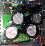
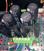
I have specified 10 ampere discrete Schottky diodes for the bridge rectifier, mounting two diodes per heatsink (Aavid 5132 or 5131) with thermal insulator pads between each diode and the heatsink. Schottkies were chosen because of their significantly lower forward voltage drop, which produces significantly lower power dissipation. Power dissipation is a concern because the diodes are mounted next to the large electrolytic filter capacitors. High temperature reduces capacitor lifetime, so we want low temperature, so we want low power dissipation in the PSU, so (I conclude) we want Schottky diodes.
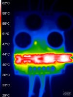
THESE THINGS GET WARM!
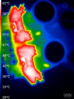
Figures 3, 4, and 5 show infrared camera images of this PSU board operating at above-maximum load. It's delivering +27V at 4 amps, and also delivering -27V at 4 amps. I took the photos after 90 minutes of running at this condition. With ambient air at +27C, the heatsink temperature was +61C and the hottest spot on the electrolytic capacitors was about +50 or +51C. In my opinion, this is comfortably below the maximum operating temperature of the caps (+85C) and they will live a long and healthy life. Especially when you consider that the test conditions (constant max-DC current into a load resistor) are much worse than anything possible when playing music into loudspeakers. I've attached an application note by Cornell Dubilier (a well-respected manufacturer of electrolytic capacitors) that walks through Operating Life calculations for capacitors at elevated temperatures, if anyone wants to pursue that further.
I recommend using the two inch tall heatsinks called "Aavid 5132". Although DigiKey stocks and sells them, regrettably Mouser has a minimum order quantity of 750 pieces (!). Mouser does stock and sell the 1.5 inch tall version called "Aavid 5131". It does a good job but of course the taller heatsink does a better job. If you plan to run your chip amp at very high loudness for long periods of time, I recommend you expend the extra effort to buy the two inch tall 5132's from DigiKey. On the other hand, if you don't forsee blasting your chipamp at max loudness very often, I think you will be just fine with the 1.5 inch tall heatsinks that have no minimum order quantity.
OTHER COMPONENTS
Resistors R3 and R4 are "bleeders", which discharge the capacitors to zero volts when the power is turned off. This is a safety measure to protect repair personnel. R5 and R6 are current limiting resistors that set the current in power-OK indicators LED1 and LED2.
Each transformer secondary is connected to a snubber, which prevents LRC oscillatory ringing. The snubbers are (MOV1 + C1 + R1) on the positive supply, and (MOV2 + C2 + R2) on the negative supply. {"MOV" is an acronym for Metal Oxide Varistor; it's a bidirectional voltage clamp used in surge surpressors.} Snubber component values were chosen after testing on the Quasimodo test jig {described elsewhere on diyAudio} and verified on a completed amplifier using two LM3886s, playing music at full volume. MOV1 and MOV2 each have a capacitance of about 550 picofarads, which is the "Cx" component of the snubber. In addition to snubbing, the MOVs also provide a measure of protection against surges on the AC mains. However, if you are uncomfortable using MOVs in your PSU, feel free to replace them with 100V, 680pF film capacitors.
CHECK OUT THE DETAILED PARTS LIST
There's a spreadsheet attached to this post, which contains a very detailed Parts List for the PSU for Chipamps. Extra detail has been included to make it easy for you, the builder, to find parts whose electrical performance is acceptably good and whose physical size will fit the PCB. If one or more parts are out of stock or backordered, the Parts List is your savior. It will help you find a replacement that's just as good or better.
Also attached is a web link to a Mouser.com preloaded Shopping Cart. A so-called "one click" Shopping Cart. BEWARE: don't shut off your brain when using this; check to be sure that every line item is in stock and not backordered. Check to be sure you're not accidentally ordering 1000 of something. Be mindful.
HOW AND WHERE CAN YOU OBTAIN THE BARE BOARDS
I've got a few dozen extra boards that I'll sell for $2/board plus shipping. They're 1oz copper with gold "ENIG" pads. Maybe you might want to also order some Super Gain Clone chipamp boards and/or soem Compact3886 chipamp boards at the same time. At the moment (Nov 2019) I'm charging $2/board no matter which board you're buying. Shipping is $6 per order to USA addresses, and $16 per order to rest of world. Max 10 boards (total) per customer. PM me with quantity desired and to get my PayPal info.
If those boards sell out and there is additional demand, I'll organize a Group Buy in the GB section of the Forum. And if there is LOTS of demand, I'll show the numbers to the diyAudio Store people, maybe they might want to eventually offer these boards through the Store.
_
The PSU circuit schematic is shown in Figure 1, and its parts placement is shown in Figure 2, below. The PSU connects to a dual-secondary power transformer and provides dual rail (± XX volts DC) DC output voltages. The capacitors are rated for a maximum of 50V, and the diodes are rated for a maximum of 100V. This is plenty, since the chip amps themselves (LM3886) are only rated for an absolute maximum of ±42V supplies. Your power transformer's secondary voltage should be 30V AC (rms) or less, to avoid violating the LM3886 maximum rating on its DC supplies.
I have specified 10 ampere discrete Schottky diodes for the bridge rectifier, mounting two diodes per heatsink (Aavid 5132 or 5131) with thermal insulator pads between each diode and the heatsink. Schottkies were chosen because of their significantly lower forward voltage drop, which produces significantly lower power dissipation. Power dissipation is a concern because the diodes are mounted next to the large electrolytic filter capacitors. High temperature reduces capacitor lifetime, so we want low temperature, so we want low power dissipation in the PSU, so (I conclude) we want Schottky diodes.
THESE THINGS GET WARM!
Figures 3, 4, and 5 show infrared camera images of this PSU board operating at above-maximum load. It's delivering +27V at 4 amps, and also delivering -27V at 4 amps. I took the photos after 90 minutes of running at this condition. With ambient air at +27C, the heatsink temperature was +61C and the hottest spot on the electrolytic capacitors was about +50 or +51C. In my opinion, this is comfortably below the maximum operating temperature of the caps (+85C) and they will live a long and healthy life. Especially when you consider that the test conditions (constant max-DC current into a load resistor) are much worse than anything possible when playing music into loudspeakers. I've attached an application note by Cornell Dubilier (a well-respected manufacturer of electrolytic capacitors) that walks through Operating Life calculations for capacitors at elevated temperatures, if anyone wants to pursue that further.
I recommend using the two inch tall heatsinks called "Aavid 5132". Although DigiKey stocks and sells them, regrettably Mouser has a minimum order quantity of 750 pieces (!). Mouser does stock and sell the 1.5 inch tall version called "Aavid 5131". It does a good job but of course the taller heatsink does a better job. If you plan to run your chip amp at very high loudness for long periods of time, I recommend you expend the extra effort to buy the two inch tall 5132's from DigiKey. On the other hand, if you don't forsee blasting your chipamp at max loudness very often, I think you will be just fine with the 1.5 inch tall heatsinks that have no minimum order quantity.
OTHER COMPONENTS
Resistors R3 and R4 are "bleeders", which discharge the capacitors to zero volts when the power is turned off. This is a safety measure to protect repair personnel. R5 and R6 are current limiting resistors that set the current in power-OK indicators LED1 and LED2.
Each transformer secondary is connected to a snubber, which prevents LRC oscillatory ringing. The snubbers are (MOV1 + C1 + R1) on the positive supply, and (MOV2 + C2 + R2) on the negative supply. {"MOV" is an acronym for Metal Oxide Varistor; it's a bidirectional voltage clamp used in surge surpressors.} Snubber component values were chosen after testing on the Quasimodo test jig {described elsewhere on diyAudio} and verified on a completed amplifier using two LM3886s, playing music at full volume. MOV1 and MOV2 each have a capacitance of about 550 picofarads, which is the "Cx" component of the snubber. In addition to snubbing, the MOVs also provide a measure of protection against surges on the AC mains. However, if you are uncomfortable using MOVs in your PSU, feel free to replace them with 100V, 680pF film capacitors.
CHECK OUT THE DETAILED PARTS LIST
There's a spreadsheet attached to this post, which contains a very detailed Parts List for the PSU for Chipamps. Extra detail has been included to make it easy for you, the builder, to find parts whose electrical performance is acceptably good and whose physical size will fit the PCB. If one or more parts are out of stock or backordered, the Parts List is your savior. It will help you find a replacement that's just as good or better.
Also attached is a web link to a Mouser.com preloaded Shopping Cart. A so-called "one click" Shopping Cart. BEWARE: don't shut off your brain when using this; check to be sure that every line item is in stock and not backordered. Check to be sure you're not accidentally ordering 1000 of something. Be mindful.
HOW AND WHERE CAN YOU OBTAIN THE BARE BOARDS
I've got a few dozen extra boards that I'll sell for $2/board plus shipping. They're 1oz copper with gold "ENIG" pads. Maybe you might want to also order some Super Gain Clone chipamp boards and/or soem Compact3886 chipamp boards at the same time. At the moment (Nov 2019) I'm charging $2/board no matter which board you're buying. Shipping is $6 per order to USA addresses, and $16 per order to rest of world. Max 10 boards (total) per customer. PM me with quantity desired and to get my PayPal info.
If those boards sell out and there is additional demand, I'll organize a Group Buy in the GB section of the Forum. And if there is LOTS of demand, I'll show the numbers to the diyAudio Store people, maybe they might want to eventually offer these boards through the Store.
_
Attachments
-
 Figure_schematic.png69.3 KB · Views: 6,041
 -
 Diodes_rear.JPG313 KB · Views: 1,366
 -
 Diodes_front.JPG449.6 KB · Views: 1,307
 -
 Hottest_Spot.JPG162.7 KB · Views: 6,823
 -
 Oblique_View.JPG187.7 KB · Views: 3,919
 -
 Top_View.JPG166.8 KB · Views: 4,010
 -
 PSU_Gerber_image.png35.1 KB · Views: 3,261
 -
PartsList_PSU_for_Chipamps.zip6.1 KB · Views: 455
-
Saved_Mouser_Shopping_Cart.txt119 bytes · Views: 413
-
CDE_Electrolyic_Application_Guide.pdf414.4 KB · Views: 569
Last edited:
YES!!!
Hey Mark, because I know everyone is getting geared up for this I have a parts question.
For the PSU—C1, C2:
This cap is out of stock both at Mouser and Digikey:
MKS2D036801F00KO00 WIMA | Mouser
How important is the 10% tolerance? I get it that Quasi may be less or more happy with a looser value.
This is the 20% tolerance version:
MKS2D036801F00MC00 WIMA | Mouser
Matter in the circuit?
Thanks!!
—Apologies if this should be in the PSU thread!
Last edited:
Yes the snubbing capacitors C1 and C2 can be 20% tolerance and it will not be a problem.
Thanks Mark!
3channels on one PSU?
Hi Mark,
Would it be possible to run three SGC amp boards off one PSU using a AS-3222 transformer?
Hi Mark,
Would it be possible to run three SGC amp boards off one PSU using a AS-3222 transformer?
If I could offer a criticism of the Builder’s Notes: there is no explanation offered as to why page 8 figure B is an improper method for mounting a toroidal transformer. Is it because there is not much clearance to the top plate which could cause a short if too much force is applied?
The final paragraph on page 7 attempts to explain, however the wording is clumsy and "could" is inexplicably repeated. I will change that in the next revision. Thank you!
Would it be possible to run three SGC amp boards off one PSU using a AS-3222 transformer?
I wouldn't try that, myself, not even with the full 2.0 inch tall heatsinks (Aavid 5132) that Mouser doesn't stock and DigiKey does. If I were running three LM3886 amp channels, I'd use the Universal Power Supply PCB from the Store.
However if you possess some kind of guaranteed, iron-clad proof that you'll never run the three amp channels at more than (2/3 rds) of max power, then you might decide on your own to give it a shot.
Mark, thanks for the reply.
I do have a spare store Universal PSU board. I would likely stay below 2/3rds, but no guarantees the kids would. It would be for a center and two surround channels for HT. The center would pull most of the load, but not sure how much more the surrounds would pull.
I do have 4 of your PSU board coming, so i could just run two PSU's. Would it be possible to use one Transfo and two PSU's? I'm just working out options.
Thanks for your help!
Yes it is possible to connect one transformer to two PSU boards, but the number of ways to do it wrong is huge. So if you are going to attempt it, I recommend you buy ten or even twenty pieces of your AC mains fuse. You'll blow one or two fuses per wiring mistake. And use a dim-bulb tester (good) or a Variac plus dim-bulb tester (better) during initial power-on testing.
link
link
Yes it is possible to connect one transformer to two PSU boards, but the number of ways to do it wrong is huge. So if you are going to attempt it, I recommend you buy ten or even twenty pieces of your AC mains fuse. You'll blow one or two fuses per wiring mistake. And use a dim-bulb tester (good) or a Variac plus dim-bulb tester (better) during initial power-on testing.
link
Sounds good. I have the bulb tester built but no variac. Just quickly thinking about it. Connect both PSu's in parallel to the transformer secondaries via a terminal strip. Outputs from the two PSU's would not be summed to avoid one pulling to much load. One PSU for the two surround amp boards, and one for the center channel. I could use a fuse block in place of the term strip for protection of each secondary leg to the PSU's, ie 8 fuses. Would I need to run the transformer shield wire in parallel as well?
The Universal PSU is 171x156 vs. 196x156 for two of these PSU's. So I'm not saving any space. Is there any benefit, if I got the wiring correct, to using these chip amp PSU's over the universal in this application?
Mark, Thank You for your help.
I would just fit one fuse, in series with the transformer primary(s). If your mains-input IEC connector inlet box requires two fuses then two of course. Fuses in the secondaries and/or in the DC output rails only protect against a subset of possible faults and you'll need a LOT of them. So I don't use those, myself.
The advantages of the Universal Power Supply board include
~
The advantages of the Universal Power Supply board include
- It has footprints for Fast-On blade connectors, which you may prefer
- It's one PCB not two, therefore it's conceptually simpler
- It includes an option for C-R-C filtering which some people like. (Install copper wires instead of "R" to disable this)
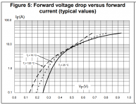
- It has footprints for three-leged TO-247 or TO-220 diodes with pinout A-K-A. This gives you the option to install the fancy new "Field Effect Rectifier Diodes" from ST Microelectronics. A good choice would be the FERD30H100 diode, whose Mouser part number is 511-FERD30H100STS. This FERD has extremely low forward voltage drop, see datasheet Figure 5. Admittedly it's a "slow" diode (reverse recovery time is a microsecond, not 75 nanoseconds), but that doesn't matter if you're using a C+RC transformer snubber with damping zeta=1. As you surely will be after consulting Quasimodo test results.
- The low forward voltage drop of a FERD (or a Schottky) means the diodes will dissipate less power (P = V * I) and produce less heat. That's valuable when trying to run three amp channels out of the same box, without cooking the electrolytic filter caps and other heat sensitive parts.
- The Universal PSU board is in the diyAudio Store, and we'd all like to support the Store with our hobby dollars.
~
Attachments
Thanks Mark!
I'll take you wise advice and use the Universal PSU for this 3ch amp. Looks like I may have a couple PSU's for Chip Amps to sell. Will Have four of them and I'm not sure I'll have a use for all them in the future.
I'll take you wise advice and use the Universal PSU for this 3ch amp. Looks like I may have a couple PSU's for Chip Amps to sell. Will Have four of them and I'm not sure I'll have a use for all them in the future.
Mark,
This should be the correct thread for transformer information. I have seen Figure 7 and 8 on the other thread, and I have looked at the build guide. So just for piece of mind, since I am new to this hobby, I will ask again:
I have a 300VA w/ 2 x 24VAC secondaries transformer (for the 3875), and 2 x 300VA w/ 2 x 22VAC secondaries transformers (for the 2 x 4780 chips). All would be 8 ohm stereo builds.
These should work correct?
MM
I recommend 200 VA transformers for use with the PSU for Chipamps PCB. This prevents you from accidentally drawing far too much output current and melting the components on the PCB. (Instead, if you draw far too much output current, the transformer windings will melt!)
But it's your DIY hobby, and your PCB; you can hook it up to any transformer you want and nobody can stop you. If you want to hook it up to a 300VA transformer, and if you accept the responsibility, go right ahead. You are responsible for choosing suitable diodes, heatsinks, and electrolytic capacitors. You are responsible for deciding whether or not to perform thermal imaging experiments at worst case conditions {see attachments to post #1}. You are responsible for choosing the AC mains fuse, namely its current rating and speed-of-blow. Etc.
But it's your DIY hobby, and your PCB; you can hook it up to any transformer you want and nobody can stop you. If you want to hook it up to a 300VA transformer, and if you accept the responsibility, go right ahead. You are responsible for choosing suitable diodes, heatsinks, and electrolytic capacitors. You are responsible for deciding whether or not to perform thermal imaging experiments at worst case conditions {see attachments to post #1}. You are responsible for choosing the AC mains fuse, namely its current rating and speed-of-blow. Etc.
Thank for input Mark. I have the heatsinks, diodes, caps, for the original P. Daniel builds. I actually made a PS that works for the 3875 build, but it looks nasty. I purchased your pcb's for the SGC first of all, and then bought extra's to use in my other chip amps. They look a lot nicer than my attempt. I will be sure not to melt anything, as I will change certain components. I also have some CRC pcb's which would work well with the chip amps also.
MM
MM
Let's be serious. 300VA vs 200VA doesn't make much difference when it comes to melting stuff in a short circuit situation.
A more realistic concern would be that a higher VA transformer will charge the PSU caps with shorter, stronger pulses. The current rating of your caps must match that. With decent caps, it shouldn't be a problem, especially as we're not dealing with a class A amp.
Another concern is the no load voltage of your transformer, vs the full load voltage. Here the higher VA works in your favour at no load, as bigger transformers have usually better regulation. It is thus less likely that you will exceed the voltage ratings of your chipamps. However, it also means that your voltage probably won't sag as much at higher power. That can translate in more heat dissipation.
And, btw, CRC doesn't make much sense with lm3886 AB amps (as with any class AB or D amps). Too low a R and you don't gain much. Too high a R and you loose power. And the PSRR of the lm3886 is good enough that there isn't anything to gain to start with.
A good article to determine your parts ratings for a linear PS: Linear Power Supply Design
- Home
- Amplifiers
- Chip Amps
- PCB available: PSU for Chipamps , such as Super Gain Clone and Compact3886