fjromero said:
ditto....dimensions to this board as well...thanks
K-amps said:One would like to think that it would be good to give people all the information and let them decide what to use based on availability/price etc.
I (respectfully), strongly disagree with this "policing" attitude of keeping information from others in hopes of allying any false fears.
The MJ2119x's are not blood Diamonds... they can be had if one wanted...
If I needed patronizing of that kind, I'd go to my mother-in-law for advice.
Maybe you are right, K-amps.
If so, in my opinion, there is no reason to get upset or use strong words.
🙂
And I have my ways and my caring or parenting attitude are a part of me.
It wont change much because of this.
I am too old to change in this matter and even if I could, I wouldn't want to.
I will continue to base my audio advices regarding transistor choice moderated,
while keeping a thought onto all which I am possibly talking to
and try to imagine what can be like, where some of my readers are living.
And sure is, that the topic and context ,where I contribute my words,
will make a difference what I say.
I don't blame those with another approach than me, too much. Only little.
They do it their way, in their full rights.
There are plenty enough around here doing most things differently
than
lineup
...........................................................................
I see you went for MJ15003 / MJ15004, fjromero
And PCB has got option for 4 pairs. This will do good!
Nice PCB works ...
I am sure there are several others, not posting 😉
that will try this amplifier project.
Because I see there are new members asking for 300-400 Watt amplifiers every week.
Some never can get enough of that power.
It is a like drug in DIY

lineup
I agree, there is so much DIY demand for 300-500watters that it is amazing we do not have a lot more "makeable" and modern designs.
Nelson, maybe this is your next calling. 🙂
Nelson, maybe this is your next calling. 🙂
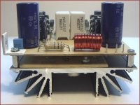
The real dimensions of the PCB, they are 140x96 for the part of control and 276x68, for the part of the end.
Greetings
Greetings
Photos the 400w.
regeards
regeards
An externally hosted image should be here but it was not working when we last tested it.
An externally hosted image should be here but it was not working when we last tested it.
An externally hosted image should be here but it was not working when we last tested it.
An externally hosted image should be here but it was not working when we last tested it.
edl said:hmmm. I had two pairs of MJ15003/15004 Onsemi samples. They measured 280V Vceo! 😎
I take it you measured BVceo, and not Vceo(sus).
Vceo(sus) at 200 mA is a different beast.
If you try Vceo(sus) on these at 200 mA, I suspect you will find the device cramps up.
Cheers, John
fjromero said:
Hola ! 😀
ThankYou for schematics and PCB ! 🙂
I like a lot this schematics above all for the symmetry of the project.
This amp remembers me for some aspects the Leach.
I think that the result will be really excellent!

bye 🙂
Here teneis the PWB for 200 or 400 w, the schemes and the PWB of the end, ok working to the 100%.
The schemes are equal, but with the opportune modifications, like the PWB of control.
greetings
The schemes are equal, but with the opportune modifications, like the PWB of control.
greetings
An externally hosted image should be here but it was not working when we last tested it.
An externally hosted image should be here but it was not working when we last tested it.
An externally hosted image should be here but it was not working when we last tested it.
An externally hosted image should be here but it was not working when we last tested it.
An externally hosted image should be here but it was not working when we last tested it.
Photos the 200 w.
An externally hosted image should be here but it was not working when we last tested it.
An externally hosted image should be here but it was not working when we last tested it.
An externally hosted image should be here but it was not working when we last tested it.
An externally hosted image should be here but it was not working when we last tested it.
An externally hosted image should be here but it was not working when we last tested it.
fjromero 200 watt and 400 watt amplifier
.
.
.
! fjromero !
.
.
.
😎 COOL 😎
amplificador superba!
grazias a la muchos!
😎 COOL 😎
lineup
Lineup Audio
http://lineup.awardspace.com/
.
.
.
! fjromero !
.
.
.
😎 COOL 😎
amplificador superba!
grazias a la muchos!
😎 COOL 😎
lineup
Lineup Audio
http://lineup.awardspace.com/
Attachments
I think that will not be warmed up, to see the photo.
Greetings
Greetings
An externally hosted image should be here but it was not working when we last tested it.
hello
is it me or did you put the tip41 and tip42 wrong? base is placed where the emitter is supposed to be... ¿? the amplifier would work great with an oscilloscope as a heavy load...
regards
dr tube
is it me or did you put the tip41 and tip42 wrong? base is placed where the emitter is supposed to be... ¿? the amplifier would work great with an oscilloscope as a heavy load...
regards
dr tube
 This forum is English Language. Translate, please.
to see if this scheme is the correct one, warm greetings.
An externally hosted image should be here but it was not working when we last tested it.
: Confused:: Confused:¿your build?: Confused:: Confused:
Hello Tupolev😀
as always sharing your diselños
Greetings, comrade.


- Status
- Not open for further replies.
- Home
- Amplifiers
- Solid State
- Pcb 300 W