I have to leave so I'll run the measurement later this evening or tomorrow, curious to see how much it deviates from the mechanical approximation. I checked and +-10% wouldn't affect the sim too much. How low should I go for measuring the tweeter and both drivers in parallel 500Hz?
I suggest to use external tools, because for a better approximation of the phase you need to first extend the measured response beyond the 20KHz limit (if your measuring system limits at this point). Set the bottom at 100Hz. I export the response to a plain text file, and then manipulate it in FRC, extending the response up to 40KHz and then calculating the minimum phase.Then convert measured responses to minimum phase. Only way I know how to do this in REW is tedious but works:
Ralf
Yeah, I meant 'wouldn't'. BUT- your plot shows a tremendous rise, more than I would have expected.
Wolf
Wolf
You can also do it with free tool by Jeff Bagby and Charlie Laub called minimum phase extractor.
Jeff Bagby's Software Page
PCD is also available in the above link.
Jeff Bagby's Software Page
PCD is also available in the above link.
Using XSim here link to guide from bwaslo how to find offset http://www.diyaudio.com/forums/multi-way/287340-xsim-critique-part-2-a-7.html#post4634286.
Minimum phase extraction seems complicated here some explanation from John K... http://www.diyaudio.com/forums/mult...ion-eq-fir-filtering-tool-12.html#post3302983
By the way Zonneschimmel as usual looks to be a nice speaker.
Minimum phase extraction seems complicated here some explanation from John K... http://www.diyaudio.com/forums/mult...ion-eq-fir-filtering-tool-12.html#post3302983
By the way Zonneschimmel as usual looks to be a nice speaker.
Last edited:
Thanks BYRTT, I'm eager to see what you're doing with the 10F and the waveguide 🙂. And I'll probably start on the test-enclosure for the 22W soon to see if I can get rid of the distortion with DIY variovents.
So I ran the measurements (gated 4 samples) and followed bwaslo's explanation here: http://www.diyaudio.com/forums/multi-way/287340-xsim-critique-part-2-a-7.html#post4634286
using the minphase responses generated through REW (export impuls minphase, import impuls, export frd) I get a delay of 1.35 inches. Quite a lot more then 0.94 mechanical.

Since this was so far off the mechanical offset and bwaslo doesn't mention using minimum phase measurements. I did it again with just the measured frd and I find 0.88 inches. Common sense leads me to believe this is the correct value. I do wonder how the minphase was so far off.
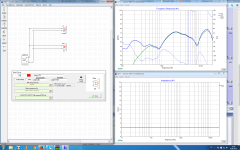
Largest difference in simulation is about 0.5dB between 0.88 and 0.94 inch delay
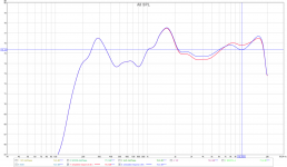
using the minphase responses generated through REW (export impuls minphase, import impuls, export frd) I get a delay of 1.35 inches. Quite a lot more then 0.94 mechanical.

Since this was so far off the mechanical offset and bwaslo doesn't mention using minimum phase measurements. I did it again with just the measured frd and I find 0.88 inches. Common sense leads me to believe this is the correct value. I do wonder how the minphase was so far off.

Largest difference in simulation is about 0.5dB between 0.88 and 0.94 inch delay

Last edited:
Thanks for doing this but that is not a good fit as the shape is all wrong despite difference values being under 1dB. It's the signature in the dips and peaks should all be like two fingerprints that land on one another. You might try the fit with the min phase version and see if it is closer in character. The acoustic offset is an odd thing and doesn't have to be less than or equal to mechanical. Did you account for cosine theta effect of mic placement relative to drivers?
10F measurement was from 100-20K, the others from 500-20K. 0.5m on tweeter axis
Just to make sure I'm following:
The first minphase fit is bad since it misses the peak at 1K --> I agree so I did the 2nd fit without the minphase adjustment to the responses.
The 2nd fit seems very good, all features are reproduced and the max deviation is 2dB at 900Hz peak and 15K peak. Also the acoustic offset of 0.88 inches is very close to the calculated mechanical offset of 0.94inches.
The 0.94 inches as calculated using trigonometry at 0.5m on tweeter axis. Why would I have to account for cosine theta effect in Xsim? It should allready be in the measurements.
I meant the offset you get from Xsim has cosine theta effect. When reporting acoustic offset - usually means an axial (z axis only) offset from assumption of flat baffle. Basically info to allow a builder to add a baffle setback if so desired to get time alignment.
Ah, okay. So total offset is 0.88inch and the one I'll be using to design flat on tweeter axis 0.5m away. The cos theta offset for 0.5m away and 10cm driver spacing is ~10mm or 0.39inch
Acoustical offset is total offset minus cos theta offset or: 0.49 = 0.88 - 0.39
Acoustical offset is total offset minus cos theta offset or: 0.49 = 0.88 - 0.39
Xsim with acoustical offset of 0.88inch and real values, crossover point is bit over 4K.
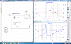
Looks good.
Anything else I missed?
Some unanswered questions from the first post:
Does the series order of components matter? I can think of 1 reason: Ease of layout for the crossover, any others?
What is acceptable as far as impedance peaks and impedance phase rotation?
What quality of components would you recommend?
Crossover layout: keep coils and caps that aren't doing the same thing 90° rotated vs each other. Any big no no's?
What type of screws do i need to screw the crossover board to the dynavox speaker binding post backside?
Hope not to interfere too much and not that i'm professor this offset subject but have some comments : )
Acoustic center in a driver is not necessary same and linear over a drivers frq bandwidth because some acoustics is created somewhere in cone and some can be from other parts example dust cap, therefor when using the method to get LF and HF part to overlay nice with the summed measurement focus on the frq area with center around planned XO point.
Suggest because you on USB mic then before export frd-file from REW use "Estimate IR delay" button. If you on latest REW version its possible to help USB mic's with time of flight data ticking on new feature "Use acoustic timing reference", it needs a real speaker or tweeter set up via other channel to fire before the real sweep.
Regarding how correct phase plot is extracted into REW and reading John K... notes on subject linked in post 27 think it concerns me sweep is not all way from down DC potential, have seen lot of data from other members and pro's where they via control of SPL sweep tweeters down from DC without any damage, or as protection one can do as eriksquires suggest in his guide that if capacitor is used for tweeter sweep then use same capacitor or value for mid-woofer. Link to FRC program shared in post 25 (thanks geralfino) claim very wide band minimum phase extraction tool, that sounds good and goes hand in hand with notes by John K... so maybe its a superior tool for true phase. The guide from xrk971 about export/import IR to have minimum phase extracted into REW think he learned from another thread or member (correct me if wrong 🙂) and think that procedure was more meant to be used with special scenario using FDW set to 1/6 oct 4,3 cycles window, which ensure less interference into measurement and thereby a cleaner raw data set to let REW engine calculate true minimum phase. Should you want to try FDW for this project or the big ones in your living room : ) which wesayso use a lot and show excellent performing system data although his best FDW results are based from DRC engine, it would be very easy take your saved mdat session and follow point 3 in this post 907 guide http://www.diyaudio.com/forums/mult...ion-eq-fir-filtering-tool-91.html#post4583199 before export frd-files for XSim. If you try FDW then try keep an eye on phase results and if you all over by this method get more easy task to have a calibrated system when summed.
In post 1 is asked what components quality to order, well except as young i was a brand snob will say thru life have heard excellent sound from both cheap and expensive components, even electrolytic caps wired back to back example Panasonic FC or Nichicon FG can for me sometimes measure and sound as good as the exotic ones.
Last edited:
As usual it will probably take me a week before I really, really get what it is you're saying 🙂. You have a way of thinking on a level of abstraction a bit higher then mine so it can take some time before I get the "Aha-erlebnis"
I allways use a 4 sample window if I can and used the export/import IR to feed Rephase and setup my main FIR system but in this case I'm not too worried about mistakes because I always go through a long measuring-fine tuning phase with all drivers playing. This for me is the biggest benefit of DSP and active speakers, you can just keep measuring/listening until it's good without having to go out and buy coils or caps.
I also read a lot about people not liking USB mics because you can't get super accurate timing data like you can via partial loopback measurements. So the new REW "use acoustic timing reference feature" looks very interesting.
From an academic point of view I find the discussion very interesting. When measuring and using those measurements for simulation it's important to know what else is going on and how those things affect the measurements and the resulting simulation.
From an engineering point of view it's also important to know what will happen to the simulated result in the real world and I have doubts about the necessity considering I'll be using components with tolerances of 10% in the crossover and will not keep my head at the exact same place while listening. There is also a difference in the effort I go through building desktop pc speakers and a reference level main audio system. But I can already hear my B&W center speaker begging for a DIY replacement and the main reason I'm on this forum is to learn so might as well do so now.
Okay, so I read some stuff, tried to get the acoustic reference working in REW (didn't succeed, gave results of 0.22 inch delay, even smaller than cos theta...)
So I got tired of all the theoretical stuff and just did it the same way as for my main speakers: program LR2 @ 4K in Najda, hook tweeter and 10f up in same polarity and adjusted delays for biggest dip.
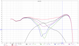
3 samples = 0.21cm = 0.82 inch tweeter delay gave the biggest dip.
So I got tired of all the theoretical stuff and just did it the same way as for my main speakers: program LR2 @ 4K in Najda, hook tweeter and 10f up in same polarity and adjusted delays for biggest dip.

3 samples = 0.21cm = 0.82 inch tweeter delay gave the biggest dip.
Hope not to interfere too much and not that i'm professor this offset subject but have some comments : )
Acoustic center in a driver is not necessary same and linear over a drivers frq bandwidth because some acoustics is created somewhere in cone and some can be from other parts example dust cap, therefor when using the method to get LF and HF part to overlay nice with the summed measurement focus on the frq area with center around planned XO point.
Suggest because you on USB mic then before export frd-file from REW use "Estimate IR delay" button. If you on latest REW version its possible to help USB mic's with time of flight data ticking on new feature "Use acoustic timing reference", it needs a real speaker or tweeter set up via other channel to fire before the real sweep.
Regarding how correct phase plot is extracted into REW and reading John K... notes on subject linked in post 27 think it concerns me sweep is not all way from down DC potential, have seen lot of data from other members and pro's where they via control of SPL sweep tweeters down from DC without any damage, or as protection one can do as eriksquires suggest in his guide that if capacitor is used for tweeter sweep then use same capacitor or value for mid-woofer. Link to FRC program shared in post 25 (thanks geralfino) claim very wide band minimum phase extraction tool, that sounds good and goes hand in hand with notes by John K... so maybe its a superior tool for true phase. The guide from xrk971 about export/import IR to have minimum phase extracted into REW think he learned from another thread or member (correct me if wrong 🙂) and think that procedure was more meant to be used with special scenario using FDW set to 1/6 oct 4,3 cycles window, which ensure less interference into measurement and thereby a cleaner raw data set to let REW engine calculate true minimum phase. Should you want to try FDW for this project or the big ones in your living room : ) which wesayso use a lot and show excellent performing system data although his best FDW results are based from DRC engine, it would be very easy take your saved mdat session and follow point 3 in this post 907 guide http://www.diyaudio.com/forums/mult...ion-eq-fir-filtering-tool-91.html#post4583199 before export frd-files for XSim. If you try FDW then try keep an eye on phase results and if you all over by this method get more easy task to have a calibrated system when summed.
In post 1 is asked what components quality to order, well except as young i was a brand snob will say thru life have heard excellent sound from both cheap and expensive components, even electrolytic caps wired back to back example Panasonic FC or Nichicon FG can for me sometimes measure and sound as good as the exotic ones.
Byrtt, you are probably right. The proper took to use for example is the minimum phase extractor and frequency blender by Charlie Laub and Jeff Bagby.
FRD Blender and Minimum Phase Extractor
Okay, so I read some stuff, tried to get the acoustic reference working in REW (didn't succeed, gave results of 0.22 inch delay, even smaller than cos theta...)
So I got tired of all the theoretical stuff and just did it the same way as for my main speakers: program LR2 @ 4K in Najda, hook tweeter and 10f up in same polarity and adjusted delays for biggest dip.
View attachment 557336
3 samples = 0.21cm = 0.82 inch tweeter delay gave the biggest dip.
That's one way to do it - step through delays to get deepest null then flip polarity back. You may be off by more than one cycle though as that can still give deep null so check for that.
I prefer to measure in situ as much as possible. Theory is good and necessary to guide the way during development and in order to interpret any measurements but I think in audio it's very difficult (at least for me) to take "everything" into account. If you forgot something the measurement will tell you or it wasn't that important for the specific case.
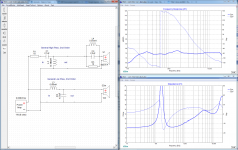
I changed acoustic offset to 0.82 and fiddled a bit with the values. The only change made from the previous version was C3 from 3.9 to 4.7. I just ordered the parts at Strassacker.

I changed acoustic offset to 0.82 and fiddled a bit with the values. The only change made from the previous version was C3 from 3.9 to 4.7. I just ordered the parts at Strassacker.
- Status
- Not open for further replies.
- Home
- Loudspeakers
- Multi-Way
- PC desktop speakers