Shaan,
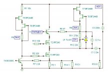
there is a small positive fb loop from the supply via the 4K7 to the gate of the mosfet CCS. With positive going signal, supply sags a little, this pulse is passed through the 4K7 to the gate, and output rises just a little. The effect is small, but non-linear. It could be eliminated by splitting the 4K7 into two 2K2 in series, with a 47uF bootstrap cap from the mid-point to the ground. This ensures that the supply for the lower gate is referenced to ground, and will it will reduce distortion. [snip]Hugh
Hello Hugh,
Nice catch on the pos feedback loop. Not wanting to split hairs, a bootstrap cap is normally returnd to the output instead of ground. That way, the midpoint moves up and down with the output making the voltage across the lower 2.2k, and current through it, constant.
Not sure what that does with the turn on/off thump though, has to be checked in practise.
jd
Understood. I tried the config you suggested many times and am well aware of its advantages. I think I will apply it... very small modification. Thanks.Shaan,
there is a small positive fb loop from the supply via the 4K7 to the gate of the mosfet CCS. With positive going signal, supply sags a little, this pulse is passed through the 4K7 to the gate, and output rises just a little. The effect is small, but non-linear. It could be eliminated by splitting the 4K7 into two 2K2 in series, with a 47uF bootstrap cap from the mid-point to the ground. This ensures that the supply for the lower gate is referenced to ground, and will it will reduce distortion.
I do not hate gate stoppers. In fact the follower becomes unstable as soon as I remove the resistor from the upper FET or, I don't know why, place a resistor in the CCS FET's gate. Not using one makes it behaving as it should. So I omit that.I do suggest gate stoppers too, it may be OK in the present form, but gate stoppers take care of the hexfet tendency to oscillate by slowing charge transfer to and from the gate junction, which is a cap, in fact. You can't be too careful here, particularly as the amp must drive a highly reactive speaker.
Nice circuit! Have you had a good listen? The harmonic profile of these very simple circuits is the hallmark of NP's designs, and very nice to listen to.
Cheers,
Hugh
Thanks. All credits goes to Mr. Pass and Mr. Macura.
Have I had a good listen?! To tell you the truth, the amp hasn't been turned off for about last three days and is playing Ronny Jordan at the time of writing this. 🙂 At night I am leaving it on, burning silently.
I am playing whatever I have in my archives. One after another. No complain so far. It's (almost) a perfect amplifier(with DoZ pre 🙂 ).
Hugo,
I don`t know about that many deleted posts and pronounced warnings (just one), a punishment may be legitimate anyway.
I don`t know about that many deleted posts and pronounced warnings (just one), a punishment may be legitimate anyway.
Hi Hugh;
this 47 uF cap will definitely give a thump on switching off of the amp.
Gate stopper will introduce a pole with input capacitance of MOSFET
Hi Anatoliy,
Yes, there is a thump, but it's infrasonic, hardly noticeable.
Yes, there is a pole, no question, defined by RC, but again, this is common practice to sidestep potential instabilities, and introduces no sonic penalties, why not?
Hugh
I don't think so. It would be better if quiescent current of the whole output stage goes down when the amp is switched off, instead of abrupt discharge of the coupling capacitor through the CCS and a speaker..
Because such a pole can cause oscillations, while without it the CCS may be stable. According to what Shaan writes it is stable.
Thanks both. The config looks interesting, so I will try it. If it oscillates, I will just have to remove that capacitor, and there I get my 4K4(~4K7 🙂 ) back.
No problem guys! thanks.
Howdy,
since that resistor acts as a current source, it should be preferably replaced with an active high impedance arrangement (will give a cleaner voltage at the gate without causing any spike).
since that resistor acts as a current source, it should be preferably replaced with an active high impedance arrangement (will give a cleaner voltage at the gate without causing any spike).
Howdy,
since that resistor acts as a current source, it should be preferably replaced with an active high impedance arrangement (will give a cleaner voltage at the gate without causing any spike).
The BJT you see in the gate is THE last "active" device I can afford(due to limited space and for the sake of simplicity).
A little bit of spike is perfectly okay for me as long as the FM channels are alive while the follower is on(I don't own a scope, so I never know how much spike is there at any time, however).
But of course I encourage you if you want to make one. If you don't, just fine, I know you don't like it.
Thanks.
Hugh,
Who will benefit from encouraging theoretically or technically incorrect claims? You should know that I do usually declare my viewpoints supported by factual detail, although not every time.Work it out for yourself, Sir. You are super critical, encourage no one, and seem hell bent on upsetting the denizens here.
Not sure why you'd want to do this....... if you are possessed of knowledge, you might try explaining and sharing it.
shaan,
I do like it, see post #24.
Nice. I'm happy to know that. Now place the active CCS there in place of the 12K resistor and like it more. This is really great. Hope it'll sound cool. Good job.
Hugh,
Who will benefit from encouraging theoretically or technically incorrect claims? You should know that I do usually declare my viewpoints supported by factual detail, although not every time.
😎😎😎
Attachments

OT, my apologies.
Two points:
1. To learn something, people often need to be disabused of their prevailing ideas. If you confront, their eyes glaze over, pride intervenes, and they do not learn. If you are humble, logical and gentle, they 'own' the new idea, and they learn.
2. The concept of 'correct' notions, 'competent' design, etc, is the language of the high priesthood massaging their egos, consolidating their position. What is correct this decade may well be reversed next decade anyways, and there is hidden moral imperative in what you say. Know thyself, Lumba.
Back on topic:
Your idea of a CCS supplying the gate voltage is a good one, I use it too, and it works very well, no thump, particularly if a cap is placed from gate to ground to slow switch-on.
Hugh
Who will benefit from encouraging theoretically or technically incorrect claims? You should know that I do usually declare my viewpoints supported by factual detail, although not every time.
Two points:
1. To learn something, people often need to be disabused of their prevailing ideas. If you confront, their eyes glaze over, pride intervenes, and they do not learn. If you are humble, logical and gentle, they 'own' the new idea, and they learn.
2. The concept of 'correct' notions, 'competent' design, etc, is the language of the high priesthood massaging their egos, consolidating their position. What is correct this decade may well be reversed next decade anyways, and there is hidden moral imperative in what you say. Know thyself, Lumba.
Back on topic:
Your idea of a CCS supplying the gate voltage is a good one, I use it too, and it works very well, no thump, particularly if a cap is placed from gate to ground to slow switch-on.
Hugh
Dear all,
I am trying to source one transformer for my next two channel power buffer: I only found one 225VA with 2*18VAC, which could give +/-6A...
Will this one be too compromised for this duty?
Thanks in advance.
M
I am trying to source one transformer for my next two channel power buffer: I only found one 225VA with 2*18VAC, which could give +/-6A...
Will this one be too compromised for this duty?
Thanks in advance.
M
Hi Max,
Would a 42V rail, with 2.5A be sufficient for each buffer?
If so, then you need a single 225VA toroid with two 30Vac windings. Each winding could then supply one channel, with its own rectifier and filter caps. I'd suggest two caps for each channel, each around 22,000uF at 50VW, with one cap wired direct to rectifier, and the other cap in parallel but separated from it with two 0.15R 3W resistors. Duplicate, of course, for the other channel.
Such a supply is quiet, inexpensive, and very good sonically.
You will need a lot of heatsinking, since each device will be dissipating around 21 x 2.5 = 52.5 watts. There will be some voltage droop at the supply, probably to around 40V, so it's not as bad as it looks. Aim for two VERY large heatsinks, consider liquid cooling, or maybe a microprocessor cooler from a powerful PC. However, the sound these buffers produce is well worth it; it's transcendental and something you cannot forget, the amp equivalent of electrostatics.
Cheers,
Hugh
Last edited:
Hi,
this is a very good CCS, but there are other possibilities.
I would go in this direction regarding the "multiplier".
It is almost my Tower output stage. 😀
Dear Hugh,
Thank you for your extensive and quick reply.
I am stuck with my plan about using -ECdesigns'- "floating charge transfer supply" which needs dual, center tapped Tx:
Picasa Web Albums - mauricio
Of course with higher power, higher voltage active devices.
This will be followed by a "PowerReg", a power regulator which uses a gyrator.
For that I need 18*2VAC. This kind of approach prouved worthy. 😎 very silent supply, makes transparent amps...
(I don't know if it is good to make a "floating" amp...😕 )
I found a 300VA surplus TX at Plitron at convenient price. That one shall give 4amps per channel. I hope no one is reading this...
Cheers,
M
Dear Max,
If EC Designs is who I think it is - John Brown from the Nederlands - you might be right. I had a good look at the picture, and it appears to reduce and lengthen the charge cycle which is very high from a rectifier bridge, thereby reducing intermodulation with the earth return signal from the amplifier. It's VERY clever, I like it a lot, and might do something along this line myself. I use a common mode choke to do something similar between the two charge caps, but I think EC Designs system is smarter...... though the component count is higher.
I have not had much sonic success with gyrators, although their operating principle is very interesting. Often extremely elegant engineering concepts don't actually sound much good, I've found. A bit like treating liver disease with interferon, if you get my drift.....
Cheers,
Hugh
I found a 300VA surplus TX at Plitron at convenient price. That one shall give 4amps per channel. I hope no one is reading this...
I am. But I would need two, so it's all yours 😉
Max or Hugh, have you used one of these 'charge transfer power supplies'? Looks interesting, conceptually it looks like a current limiter in series with the rectifier. I would guess though that the final DC would be relatively low wrt the secondary voltage - perhaps only half. Any experience?
jd
jd
- Status
- Not open for further replies.
- Home
- Amplifiers
- Solid State
- Pavel's MOSFET Follower - No Darlington Mod