
Pavel:
"And at pic is fitting of output mosfets..."
So its not "Common emmitter, floating cooler"!
How do you isolate the bars from the cooler?
From what (nice!) kind of material they are?
Thank You for the inspiring pics"
Heinz!
"And at pic is fitting of output mosfets..."
So its not "Common emmitter, floating cooler"!
How do you isolate the bars from the cooler?
From what (nice!) kind of material they are?
Thank You for the inspiring pics"
Heinz!
Prisms are gold plated copper. Insulation from heatsink is mica or some insulation material with good thermal conductivity...
There is nothing to be sorry about, those pic's are great🙂I'm sorry for bad quality of pics...
Steen😎
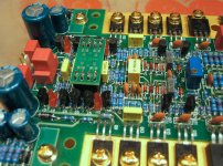
Upupa Epops said:It's prototype of my new amp with EC, cca 350-400 W into four Ohm ( still in developement )...Prisms in middle are output terminals ( there will be screwed round bars, which lead directly to binding posts ). And at pic is fitting of output mosfets...
Beautiful! Thanks for posting these.
Upupa Epops said:And whatabout make it like this, Klaas ? 😎
IMMACULATE WORKMANSHIP ......Upupa Epops🙂
Cheers,
K a n w a r
Do you agree on this Upupa ?This fits the philosophy of closing the local loops.
Your pcb implies you do it different, or perhaps i should have looked more closely 😉 ?
Klaas
Little about my design philosophy : At every amps I have PA and PS at the same PCB. This solution give shortest rail and ground traces and if is good designed, nobody can't make some mistake by completation ( similar conception have Dan Agostino at his new types of Krell ). Also at every amps I'm using copper or aluminium bars for output and driver + VAS transistors. This solution have several advantages : bars can be used like quite precise rail with really great diameter. Thermal coupling between output devices and biasing circuit is most precise. And last advantage is, that all I can set up and control outside chassis, 'cos thermal absorbability of bars is sufficient, which also help by reparing.
Upupa Epops said:Thanks, guys 😎 I'm sorry for bad quality of pics...
Awesome work!
The pcb layout is very impressive. I like the way the whole logical
flow from power supply at one end -> OP stage -> drivers -> IP stage is
done. You have obviously put a tremendous amount of
thought into this.
What size roughly is the PCB. It looks pretty long.
Any specs for this beast?
Cheers,
Terry
PCB is 95x370 mm, if you hold it in hand, isn't so great, Terry...Parametres I can only calculate, 'cos I had made similar older types : Output power - 400 W into four, 250 W into eight. Full power bandwidht - 500 kHz. SNR - more than 120 dB, ref. to full output power. Distortion - 1 dB bellow clipping - 0.001 %, 1 kHz, 0.003 %, 20 kHz. IMD - 0.001 %...But they are only preliminary data..😎
 here is more Upupa Epops stuff.
hello Upupa Epops, could you post the pcb´s somewhere else? Telecom web says error 404, not found.
Thanks
BTW I just wonder how much does one gold-plated coper bar cost.. Nice amp!
Thanks
BTW I just wonder how much does one gold-plated coper bar cost.. Nice amp!
http://www.multiweb.cz/rima/rima9_a.html
Most of the web pages concerning DPA documentation were deleted.
Most of the web pages concerning DPA documentation were deleted.
Sorry, I messed up a bit. Now it works.kubeek said:hello Upupa Epops, could you post the pcb´s somewhere else? Telecom web says error 404, not found.
Thanks
BTW I just wonder how much does one gold-plated coper bar cost.. Nice amp!
Beautiful work Pavel. The care and attention to detail in the layout is astonishing, hell even the solder work looks like worthy of a place in the OCD hall of fame 🙂
I have just one question: when's the groupbuy on these
I have just one question: when's the groupbuy on these

This amp isn't for commercial usage, only for my own enjoy - normal amateur don't have bag of mosfets for selecting... But I'm preparing " smaller brother " of this amp, with output power 250 W / 4, 150 W / 8, where will be only four mosfet in parallel and there will be selection easier. Size of PCB will be the same, but there will be also protection circuity... This PCB will be still nicer... 😎
Upupa Epops said:... This PCB will be still nicer...
I'm not sure how, but I look forward to seeing it!
- Status
- Not open for further replies.
- Home
- Amplifiers
- Solid State
- Pavel Dudek's (Upupa Epops) amplifiers