Yes ,I must say "It´s looks very good" too.I think UE do only perfekt work.Hi built only absolute precision amplifiers. 🙂
Hey Pavel, that’s a seriously good looking board design! I hope you don’t mind, but I’ve just unashamedly ripped off your multiple paralleled emitter resistor idea for my latest design 🙂. Non-inductive resistors of a few watts are a pain to buy.
Cheers,
Glen
Cheers,
Glen
" Online " queuing of output devices look good, but isn't optimal, 'cos rail and ground traces are too long and area of " current loop " are large. If you can, send me a mail, I'll send you detailed photos of PCB...
Upupa Epops said:" Online " queuing of output devices look good, but isn't optimal, 'cos rail and ground traces are too long and area of " current loop " are large. If you can, send me a mail, I'll send you detailed photos of PCB...
I agree completely, but this is only the tracking power supply driver board for the class A output stages, so the layout in this regard isn't very critical to the amplifiers performance. I'm working on the class A output stages now, and they're layed out much differently.
Cheers,
Glen
By my opinion for such amp are the same claims like for " normal " amp ( mainly in look of stability ), maybe bigger... Probably you can to use some modern fast transistors ( and the same at driver position ), so use base stoppers ( if I can recomend to you )... 😎
I'm using 30MHz transistors, same for both driver and output. I've used the same transistors several times in similarly configured output stages. A base stopper just to the driver transistor has always kept oscillations away.
Cheers,
Glen
Cheers,
Glen
Maybe I'm too diligent 😎 ... But I will be very curious for results - class A+ is elegant solution ( althoug I had never try it ) - I don't like " fata morganas " by operations of radiators, which have ampifiing as second ( supplementary ) function.... 😉
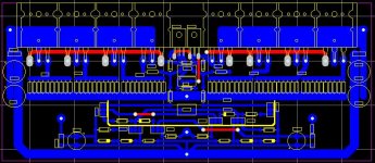
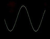
Several months ago I had show here some pics of my new amp, called TYA ( Ten Years After ). This amp was now preliminary tested and I can show you results and photos from scope. I hope, that pics of measuring will be similarly nice like these previous ones....
TYA is fullcomplementary power amp with error correction and mosfet output stage. Is designed for output power up to 400 W ( six IRF in parallel at each rail ) and rail voltage up to 70 VDC. For shortest as possible traces is designed like " all in one " - PA and PS are at the same PCB.
VAS voltage is higher than voltage at OS and are floating at them ( both supply are connected in series ). But at last tests VAS voltage was the same like " main " voltage ( for simplicity ), so output voltage was lower, 'cos output transistors wasn't open perfectly ( amp was tested by V rail max +/- 50 V).
So you must take all " data " like preliminary...
Rail voltage : +/- 50 V
Output voltage : 20 V RMS ( 100 W/ into four, 50 W/ into eight )
Frequency char. : 275 kHz - 3 dB
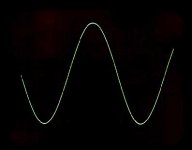
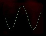
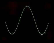
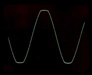
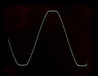
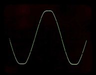
Now pics : 20 V RMS into eight, 1 kHz
TYA is fullcomplementary power amp with error correction and mosfet output stage. Is designed for output power up to 400 W ( six IRF in parallel at each rail ) and rail voltage up to 70 VDC. For shortest as possible traces is designed like " all in one " - PA and PS are at the same PCB.
VAS voltage is higher than voltage at OS and are floating at them ( both supply are connected in series ). But at last tests VAS voltage was the same like " main " voltage ( for simplicity ), so output voltage was lower, 'cos output transistors wasn't open perfectly ( amp was tested by V rail max +/- 50 V).
So you must take all " data " like preliminary...
Rail voltage : +/- 50 V
Output voltage : 20 V RMS ( 100 W/ into four, 50 W/ into eight )
Frequency char. : 275 kHz - 3 dB
Now pics : 20 V RMS into eight, 1 kHz
Attachments


- Status
- Not open for further replies.
- Home
- Amplifiers
- Solid State
- Pavel Dudek's (Upupa Epops) amplifiers