I’m surprised by the patent; I thought Amphion did this earlier, with the circular pattern of perforations flanking the midwoofer?
I’m surprised by the patent; I thought Amphion did this earlier..
..well, there's a patent, and then there is a defend-able patent. 😉
My guess is that Geithain had this "down" before Amphion (..and likely someone before them from which it was derived).
Last edited:
Another good thread (one I saw a while back, but couldn't find again):
Leaky supercardioid mids
I'm seeing that that same midbass hump (like a badly tuned BR) where I've hacked a simple hole, and not added resistive material.
Leaky supercardioid mids
I'm seeing that that same midbass hump (like a badly tuned BR) where I've hacked a simple hole, and not added resistive material.
..here is a design and manufacturer that represent prior "art":
..it's a resistance-cardioid midrange:
Gradient Revolution loudspeaker | Stereophile.com
..it's a resistance-cardioid midrange:
Gradient Revolution loudspeaker | Stereophile.com
I followed Keyser's thread with great interest then. The proto had 12" driver in a large perforated box combined with a 12" wide horn. I was pretty close to making woofer boxes like that or even better like kimmosto's KS-2125 But then I turned my head to Gradient 1.3 again. I like the lively sound of dipoles over studio-like precision and I don't have difficult reflections or modes in my room.
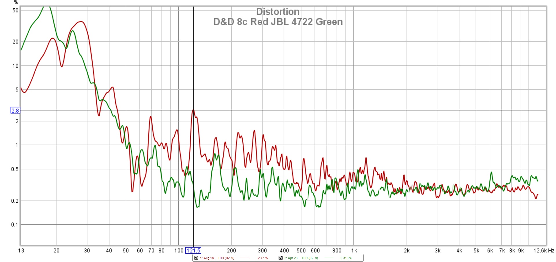
Cardioid has almost as poor efficiency as dipole in low register, that's why it must have large cone area and tolerate high power. D&D 8C has just a 8" cardioid mid and it suffers because it has to blow down to 100Hz, however loudspeaker's distortion is not easily an audible problem. Mitcho's measurement at audiosciencerewiev
If one decides to diy a cardiod, be careful to find good model to copy, and still prepare to do lots of tuning and measuring to fit it with rest of the speaker.
If the passive cardioid thing doesn't work for me (that is: if it requires a frustrating number of trials), my fallback position is to just package a nicer version of my prototype parts into simple towers - similar layout to this Lambda Unity Tower picture (from Cowan Audio website).
To me, this looks better than an Everest style box.
Thanks 🙂
You could make larger waveguides to get better low frequency pattern control. A bit of creativity and they can look really good.
A for Ara (@a.for.ara) • Instagram photos and videos
The grey ones are 1.5M across! They control their pattern much lower than my Unity horns.
Last edited:
That's loosely what I'm interested in: a visually simple tower with woofer size roughly equal to horn size. A multi driver horn will allow a much lower crossover, though, so the midbass won't have to go up as high.I followed Keyser's thread with great interest then. The proto had 12" driver in a large perforated box combined with a 12" wide horn.
Using this calculatorCardioid has almost as poor efficiency as dipole in low register, that's why it must have large cone area and tolerate high power.
Piston Excursion calculator
I guesstimate a 18" (highpassed at 100Hz) with 3-6mm Xmax will hit its limits at roughly the same SPL as the components in my prototype horn.
I'm looking at something like the LF section of the KS-2125, but bandpasssed higher e.g. aiming for 100-400Hz rather than 20-220Hz.If one decides to diy a cardiod, be careful to find good model to copy, and still prepare to do lots of tuning and measuring to fit it with rest of the speaker.
Because I'll only need a couple of octaves, and am flexible about crossover points, I'm hoping it will be a relatively quick tuning process.
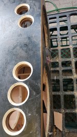
For my prototype, I'm trying light foam on the side wall perforations (some pretty chamfered holes are pictured, the other side has random shapes) and very dense stuff on the holes in the back wall (as yet untested). I'm guessing the lightly foamed holes will do almost all of the work / pattern shaping.
To keep the final version visually tidy, I think I will do something similar - I could do final tweaking by (internally) making some slots much more resistive than others. That seems like less work and mess than modifying the plywood shell.
Attachments
Last edited:
Thanks 🙂
I showed my GF a gallery of possible build styles, and that was one that got the seal of approval. Large (to ~80cm wide) is OK, as long as the exterior is visually clean and not too industrial.
You could make larger waveguides to get better low frequency pattern control [...] They control their pattern much lower than my Unity horns.
I like some of those pictures, but my size & weight limits (I'll need to be able to pick them up) mean my horn sections will have roughly the same amount of pattern control as your Unity horns.
My prototype (60x36cm mouth) should be good for 400Hz / 750Hz. That's about as big as I'd like to go, cos going much wider than the woofer(s) seems like it gives diminishing returns, and because I'd like to allow enough extra width for roundovers.
These earlier projects (link and pic) show the sort of mouth transition + overall aesthetic I'm after. I'd like to skin the horn in bamboo, hence I'm trying to keep the horn angles simple & repeatable.
seeking rear mounted driver for front horn
I'll be re-doing my Unitys later in the year as I was sick of the unfinished nailed together mdf boxes.I showed my GF a gallery of possible build styles, and that was one that got the seal of approval. Large (to ~80cm wide) is OK, as long as the exterior is visually clean and not too industrial.
No real pics for design on this PC, but 45cm flat baffle with 15cm (ea side) 15* angled wings. Rear the same and just deep enough for the Unity. Drivers above and below are AE TD15S. Built in 3 boxes/side so I can actually lift them.
This is a concern 🙂Built in 3 boxes/side so I can actually lift them.
I did some outdoor testing, and hauling my boxes in & out of the house was not easy.
---
I'm using one sealed box (the pretty one pictured in post 28) as the baseline, and a less pretty but otherwise near-identical twin as the test mule. I'm happy to chop holes in the ugly box, because I want to reduce the weight before I re-skin it with a heavy layer of bamboo. That's exactly what I did to the pictured box.
As far as I know, the earlier "Resistance enclosure" threads didn't have (or didn't show) an identical sealed box to act as a baseline. Having this baseline is amusing / frustrating. The process often goes:
1) I record an off-axis plot for the "Resistance enclosure"
2) I congratulate myself, cos it looks like a pretty good weakening of rearward radiation
3) I then realise it is only slightly better than the sealed box
Other than that, I've mostly noted noted the same things as the earlier threads.
OLD INFO, REHASHED:
(1) Running 2x15" vs 1x15" made surprisingly little difference (outdoors). Only a narrow LF band gets the sensitivity gain. I've probably seen this info before, but it seems much more real now that I've measured it myself.
(2) The simple sealed box (48cm wide) has more directivity than I really understood. It is the same as the previous point - I've seen this info before (e.g. plots of the Geddes Loudspeakers NS15), but the effect seems more real now that I've measured it myself.
POSSIBLY NEW INFO:
(3) It looks to me like any hole in the back wall dominates the pattern you get ...so I think I see why Kimmo Saunisto and then keyser went with a solid back & perforated sides. I'm measuring a figure 8 (dipole-like) pattern, with big dips 90 degrees off axis, not the cardioid-like pattern that they report.
This figure 8 pattern persists even when the holes in my back wall are much more heavily damped than those in the side walls.
(4) Despite asymmetry in the side wall holes, I get essentially symmetrical response. I chopped one side wall further, to have about 2x the surface area open than the other ...and I still get symmetrical response. Not sure if this is always true, or if it is only true because of (3).
AND, THE PRACTICAL STUFF:
(5) Outdoors, the "standard" plots for the listening position (0 vs 30 degree off axis) look better for the "Resistance enclosure" than for the sealed box.
(6) Indoors, positioned near a corner, my "Resistance enclosure" is flatter on-axis than the sealed box.
These last two points are promising, and make me think it is worth persevering. The outsdoor off-axis measurements may seem underwhelming (not much better than the baseline box), but all that actually matters is whether there is a +ve effect at the listening position.
Attachments
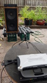
You should move those bushes in pots on the pavement between the speaker and mic when measuring. Tile floor gives "perfect reflection" now.
You should move those bushes in pots on the pavement between the speaker and mic when measuring.
I think maybe you are looking at a hose 🙂
The mic is on the little table in front of the laptop.
Tile floor gives "perfect reflection" now.
That seems right to me. I experimented with stuff to prevent ground bounce, and found that that made the notch in response worse (more complex).
Pots etc. are diffusers, pillows etc. would be dampers. Anyway sounds like you have recognized the floor bounce 😄
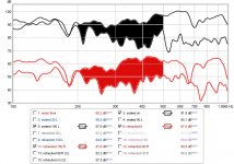
Black/yellow = sealed box, on axis vs 30 degrees off axis.
Black/blue = perforated box, on axis vs 30 degrees off axis.
Not much difference, but the perforated box is slightly 'tidier' off axis.
One has to read around the 2 big ground bounce notches... maybe next time I'll do ground plane measurements.
Black/blue = perforated box, on axis vs 30 degrees off axis.
Not much difference, but the perforated box is slightly 'tidier' off axis.
One has to read around the 2 big ground bounce notches... maybe next time I'll do ground plane measurements.
Attachments
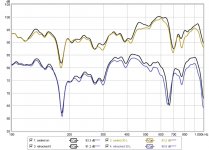
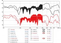
0 vs 90 degrees off axis. This is where the perforated box shines.
...so it would be throwing a bit less off-axis sound into the room.
...so it would be throwing a bit less off-axis sound into the room.
Attachments
Last edited:
Looks like REW? I love it but it can't draw directivity graphics or count DI. But taking measurements at 10¤ steps and overlaying all of the 0-90¤ (and 90-180¤ separately) would reveal the directivity "shape". Set IR gating to 6, 12, 20, 60 etc. ms and look at same measurements again. I have found 20ms and 1/12 smoothing best and then first reflections can be detected easily.
This is from ARTA and from this thread DSP midrange directivity control aka kinda cardioid

This is from ARTA and from this thread DSP midrange directivity control aka kinda cardioid
Last edited:
It is for me as I typically do it alone. The garage is on the same level as the yard where I test, but the living room is two flights up.This is a concern
True. Probably a good investment for moving other heavy things too, like fridges and washing machines. I'm off to Bunnings later today...Time to buy a six wheeled stair climbing hand truck. That will make your life a lot easier.
To finally mount the top sections in-situ, I think beers, BBQ and make a day of it with a few mates.
- Status
- Not open for further replies.
- Home
- Loudspeakers
- Multi-Way
- pattern control below 400Hz