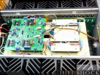

How much current do you think the Fets require on their gates to drive them?Just found a passlabs x1000.5 amp pics and was quite surprised that nelson using TO-264 package transistor to drive the 10 output mosfets?
anyway its very large transistor driving the gate capacitances of the massive ops probably makes sense but since nelson was using Toshiba mosfets as drivers I believe this could be more like a triple stage? but does super symmetry works in triple stage Output stage?
I dont know how much in specific but how is the calculated using the Gate charge method? If so in general for a 8 pair or 10 pairs of IRFp240s how much current would be required to overcome the gate capacitances?How much current do you think the Fets require on their gates to drive them?
if you search just a little , you'll find X600 or X1000 schematic floating around ...... probably for more than a decade
then all guesswork is waste of time
then all guesswork is waste of time
tried couldnt find it though... anyway the question was just to understand what sort of driver transistor required to drive the huge mosfet outputstage. I read in pass F5 manual about nelson driving about 20 pairs of mosfets with ease so what is it and how its used? I believe definitely an EF to be used. I dont know but if you have the x600 or 1000 schematic would you please share.
no EF
I'm lazy to search here for schmtc , so can't point to one
lets just say that 20mA will drive anything ...... my personal thumb of rule
example - Babelfish XJ , or JX …….. or whatever (Aleph X servo for Greedy Boyz)
Babelfish XJ , or JX …….. or whatever | Zen Mod Blog
I'm lazy to search here for schmtc , so can't point to one
lets just say that 20mA will drive anything ...... my personal thumb of rule
example - Babelfish XJ , or JX …….. or whatever (Aleph X servo for Greedy Boyz)
Babelfish XJ , or JX …….. or whatever | Zen Mod Blog
That picture is a rather later version with four dual fets on the input cascoded to Toshibas and then Fairchild parts. It really is easy to drive lots of Mosfets many early amps had probably carried over from bipolar drive stages.
The early amps had to-264 parts in a more complicated configuration.
The early amps had to-264 parts in a more complicated configuration.
Gate capacitance only becomes an issue as the Fet is switched faster and faster.I dont know how much in specific but how is the calculated using the Gate charge method? If so in general for a 8 pair or 10 pairs of IRFp240s how much current would be required to overcome the gate capacitances?
This is an audio amplifier and at 20kHZ the capacitance is minimal.
In a class D, FM amplifiers, running at 500kHZ or so in a square wave configuration, (which means to get a sharp on/off time and to maximise efficiency, there are MHZ involved), the gate capacitance becomes a problem to drive as it does in Switch Mode Power Supply design.
Thanking very much for the reply but my question is if we want to drive 10 or 15 pairs of mosfets in monster F5 at +/-80V then which driver to use? When you say just 20ma is more than sufficient then which transistor to use like a TO 264 package transistor should do the job? as if you calculate we need about sustained 20ma x 15 which is about 300ma and need a decent transistor to do that job. Can we use 2SC5200 to drive 15 pairs of IRFp240/9240 mosfets?
"one transistor driving 10 output ones - that's too simple picture of things "
besides that , I didn't say that you need 20mA in driver per each output one ;
ask mor especific question , and it'll be most probably answered
do not ask for 42 and little more , while expecting to be given even with entire mental process ,which leads to short and enlightening answer
there is FE output node , which in fact is driving OS , or part of it ....... and there is possibly even something in between ..... if nothing else than "just" biasing network
output node is point where several parts are outputting their work .... not just one transistor , be it in T0220 or T0whatever case
Last edited:
well consider I want to drive 15 pairs of IRFP240 at +/-80V in Class AB mode with IRF610 as Vbe multiplier or any 2sc5171 as Vbe multiplier. Bias can be lower as much as 15ma to 20ma per mosfet. I would like to drive a sub with it.
> 15 pairs of IRFP240 at +/-80V
As Source Followers? (How? with only one polarity.)
Then "Reverse Transfer Capacitance" of 130pFd is the key capacitance. 15 pair is 30 gates and 30*130pFd is 4,000pFd.
Assume arbitrary 1mA Vas current. Slew Rate is 1mA/4000pFd, which reduces to 0.25V/uS.
For a 80V peak in full-range music, we would like over 20V/uS.
1mA*(20/0.25) suggests more like 80mA Vas current.
Bass-only can be slower.
But pushing SR means the amplifier gets completely OUT of NFB when slewing. Ideally we like tons of headroom on this. (And can rarely reach that nirvana.)
Taking 80mA at 80V, class A Vas, we need to dissipate 6.4 Watts. (Plus a dynamic current/power.)
A BIG Vas device is one approach.
Myself I'd add a push-pull stage in the driver.
I don't see how the type of bias-multiplier or bias-level has anything to do with it.
> 15 pairs of IRFP240 at +/-80V
As Source Followers? (How? with only one polarity.)
Then "Reverse Transfer Capacitance" of 130pFd is the key capacitance. 15 pair is 30 gates and 30*130pFd is 4,000pFd.
Assume arbitrary 1mA Vas current. Slew Rate is 1mA/4000pFd, which reduces to 0.25V/uS.
For a 80V peak in full-range music, we would like over 20V/uS.
1mA*(20/0.25) suggests more like 80mA Vas current.
Bass-only can be slower.
But pushing SR means the amplifier gets completely OUT of NFB when slewing. Ideally we like tons of headroom on this. (And can rarely reach that nirvana.)
Taking 80mA at 80V, class A Vas, we need to dissipate 6.4 Watts. (Plus a dynamic current/power.)
A BIG Vas device is one approach.
Myself I'd add a push-pull stage in the driver.
I don't see how the type of bias-multiplier or bias-level has anything to do with it.
Thank you very much for the reply. Yes Im thinking of using Triple so that the VAS loading is not much hence In that case. Im thinking the large 2sc5949 / 2sa2121 as drivers. So as per the calculations you have given above I believe they can drive even 20 pairs with ease without much idle current.
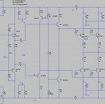
Attachments
Then "Reverse Transfer Capacitance" of 130pFd is the key capacitance. 15 pair is 30 gates and 30*130pFd is 4,000pFd.
Assume arbitrary 1mA Vas current. Slew Rate is 1mA/4000pFd, which reduces to 0.25V/uS.
For a 80V peak in full-range music, we would like over 20V/uS.
Decent enough calculation.
The peak would be 63V for each half of the balanced output stage, which
by your margin would ask for 16V/usec.
Actual product was spec'd at 40 V/usec = 20 V/usec each half. The
amp did not depend a lot on feedback for performance, and the feedback
was local to the front end on the first version, but not the .5 series.
The first version of the X1000 used TO-3P transistors in single-ended
Vas and the .5 version used TO-220's in a push-pull Vas, which maxed
out at 100 mA Class A.
They ran pretty hot, but none failed.
The biggest problem was not the capacitance of the output stage, but
the non-linearity of that capacitance. It shows up as increased distortion
at high frequencies not because of poor open loop bandwidth but actual
increased distortion in the output devices.
A version with followers to drive the output stage was also developed
but not produced, as it was not preferred by our listeners.

But have you used a TO 264 Bipolar to drive all these large bank of mosfets? I think I read somewhere about 78 mosfets? Its huge number but how were they be stable? anyway in general what is the way to overcome the capacitances of the mosfets like as much as 10 to 15 pairs of IRFP240/9240 in output stage. Just increasing the driver idle current will suffice? You said that you drove with 100ma of bias for the driver.Decent enough calculation.
The peak would be 63V for each half of the balanced output stage, which
by your margin would ask for 16V/usec.
Actual product was spec'd at 40 V/usec = 20 V/usec each half. The
amp did not depend a lot on feedback for performance, and the feedback
was local to the front end on the first version, but not the .5 series.
The first version of the X1000 used TO-3P transistors in single-ended
Vas and the .5 version used TO-220's in a push-pull Vas, which maxed
out at 100 mA Class A.
They ran pretty hot, but none failed.
The biggest problem was not the capacitance of the output stage, but
the non-linearity of that capacitance. It shows up as increased distortion
at high frequencies not because of poor open loop bandwidth but actual
increased distortion in the output devices.
A version with followers to drive the output stage was also developed
but not produced, as it was not preferred by our listeners.
There were no bipolar transistors in the amplifier.
If you go through PRR's analysis you see that the capacitance is not
nearly as much as you might imagine. The Cgd is the one that piles up
on you when you parallel lots of devices.
If you go through PRR's analysis you see that the capacitance is not
nearly as much as you might imagine. The Cgd is the one that piles up
on you when you parallel lots of devices.
I strongly suspect that this problem arises mainly because there is a large difference between the positive half and the negative half (check the datasheets from IRF240/9240).Decent enough calculation.
The peak would be 63V for each half of the balanced output stage, which
by your margin would ask for 16V/usec.
Actual product was spec'd at 40 V/usec = 20 V/usec each half. The
amp did not depend a lot on feedback for performance, and the feedback
was local to the front end on the first version, but not the .5 series.
The first version of the X1000 used TO-3P transistors in single-ended
Vas and the .5 version used TO-220's in a push-pull Vas, which maxed
out at 100 mA Class A.
They ran pretty hot, but none failed.
The biggest problem was not the capacitance of the output stage, but
the non-linearity of that capacitance. It shows up as increased distortion
at high frequencies not because of poor open loop bandwidth but actual
increased distortion in the output devices.
A version with followers to drive the output stage was also developed
but not produced, as it was not preferred by our listeners.
Even with an additional true complementary push-pull medium power follower remain (or extend) this issue.
Maybe a circlotron topology (perhaps without a follower driver stage) like that under
Build The Amazing FET Circlotron | Pass DIY
eleminates all audible effects through the unwanted non-linearities of capacitance due only one kind of power MOSFET - either the IRF240 or only IRF9240.
The term "True Complementary" (in case with NPN/PNP resp. N-CH and P-CH) unfortunately does not exist in real live.
Last edited:
- Home
- Amplifiers
- Pass Labs
- Passlabs X1000 output stage driven by a To264 transistor?